doc - Stanford University
advertisement
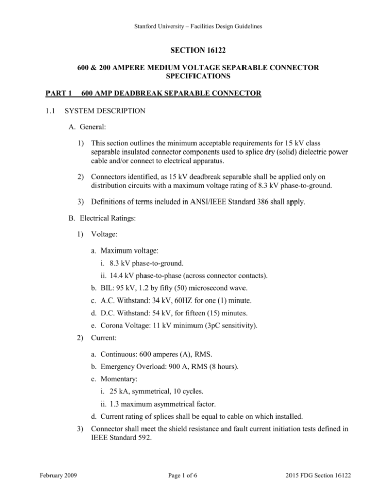
Stanford University – Facilities Design Guidelines SECTION 16122 600 & 200 AMPERE MEDIUM VOLTAGE SEPARABLE CONNECTOR SPECIFICATIONS PART 1 1.1 600 AMP DEADBREAK SEPARABLE CONNECTOR SYSTEM DESCRIPTION A. General: 1) This section outlines the minimum acceptable requirements for 15 kV class separable insulated connector components used to splice dry (solid) dielectric power cable and/or connect to electrical apparatus. 2) Connectors identified, as 15 kV deadbreak separable shall be applied only on distribution circuits with a maximum voltage rating of 8.3 kV phase-to-ground. 3) Definitions of terms included in ANSI/IEEE Standard 386 shall apply. B. Electrical Ratings: 1) Voltage: a. Maximum voltage: i. 8.3 kV phase-to-ground. ii. 14.4 kV phase-to-phase (across connector contacts). b. BIL: 95 kV, 1.2 by fifty (50) microsecond wave. c. A.C. Withstand: 34 kV, 60HZ for one (1) minute. d. D.C. Withstand: 54 kV, for fifteen (15) minutes. e. Corona Voltage: 11 kV minimum (3pC sensitivity). 2) Current: a. Continuous: 600 amperes (A), RMS. b. Emergency Overload: 900 A, RMS (8 hours). c. Momentary: i. 25 kA, symmetrical, 10 cycles. ii. 1.3 maximum asymmetrical factor. d. Current rating of splices shall be equal to cable on which installed. 3) February 2009 Connector shall meet the shield resistance and fault current initiation tests defined in IEEE Standard 592. Page 1 of 6 2015 FDG Section 16122 Stanford University – Facilities Design Guidelines C. Interchangeability: to ensure dimensional and electrical interchangeability between suppliers, the following shall apply: 1) Connector interface shall comply with the dimensional requirements of ANSI/IEEE Standard 386, bushing 600 A interface. 2) The apparatus separable connector shall be readily operable when installed to ANSI standards. 3) Components of the 600 A separable insulated connector system for apparatus connection shall be the elbow, bushing, conductor contact, plugs, cable adaptor, and shield adapter grounding device. D. Service conditions: Separable insulated connectors shall be suitable for use under the following service conditions: 1) In air, including exposure to direct sunlight. 2) Buried in earth. 3) Intermittently or continuously submerged in water. 4) Environmental temperatures within the range of -20C to +65C. 5) Connected to cables with conductor temperature as detailed below: a. Continuous, 90C b. Overload, 130C (8 hours). 1.2 QUALITY ASSURANCE. A. Testing: 1) The manufacturer shall perform one-hundred percent (100%) production testing on each item and provide certificates of compliance showing that items tested meet all electrical and mechanical requirements called for in this standard. 2) All tests shall be in accordance with test procedures outlined in ANSI/IEEE standards. 1.3 Reference: A. American National Standards Institute/Institute of Electrical and Electronic Engineers (ANSI/IEEE): Standard 386: Separable Insulated Connectors for Power Distribution System Above 600V. February 2009 Page 2 of 6 2015 FDG Section 16122 Stanford University – Facilities Design Guidelines B. Institute of Electrical and Electronic Engineers (IEEE): Standard 592: IEEE Standard for Exposed Semiconducting shields on Premolded High Voltage Cable Joints and Separable Insulated connectors. PRODUCTS 2.1 MATERIALS AND EQUIPMENT A. General: All products shall be identified in accordance with the requirements of the proposed revision to ANSI/IEEE Standard 386. B. Conductive Insulation Shields: Conductive insulation shield shall be molded EPDM Elastomeric material with a three millimeter (3.0 mm) nominal thickness. C. Bushing Accessories: 1) Bushing Accessories (feedthrough and junctions) shall have interface identical to that of the apparatus 600 A bushing. 2) Feedthrough and junctions shall be designed with molded semiconducting shields. D. Packing: 1) Connector products shall be packed in sealed plastic bags in boxes containing one complete device per box. 2) Each box shall be legibly marked with the model number, manufacturer’s name, and where applicable, insulation and conductor size that pertain to the connector contained in the box. PART 2 1.1 200 AMP LOADBREAK CONNECTOR SYSTEM DESCRIPTION A. General: 1) This section covers 15 kV class loadbreak separable insulated connectors and components used to connect dry (solid) dielectric power cable to electrical apparatus or to junctions. 2) Loadbreak insulated connectors shall be used on distribution circuits with voltage ratings 12.5 kV phase-to phase or less. 3) Definitions of terms included in ANSI/IEEE Standard 386 shall apply. B. Electrical Ratings: 1) Voltage: February 2009 Page 3 of 6 2015 FDG Section 16122 Stanford University – Facilities Design Guidelines a. Maximum voltage: i. 8.3 kV phase-to-ground. ii. 14.4 kV phase-to-phase (across connector contacts). b. BIL: 95 kV, 1.2 by fifty (50) microsecond wave. c. A.C. Withstand: 34 kV, 60HZ for one (1) minute. d. D.C. Withstand: 54 kV, for fifteen (15) minutes. e. Corona Voltage: 11 kV minimum (3pC sensitivity). 2) Current: a. Continuous: 200 amperes (A), RMS. b. Short-Time: i. 10 kA, symmetrical, 10 cycles ii. 1.3 maximum asymmetry factor. 3) Switching: ten (10) loadmake/loadbreak operations at 200 A, seventy to eighty percent (70-80 %) power factor, 14.4 kV maximum recovery voltage between contacts. 4) Fault closure: after ten (10) loadmake/loadbreak operations at 200 A and 14.4 kV contact voltage: a. 10,000 A, RMS, Symmetrical (10 cycles) 5) Insulation shield requirements: connector shall meet the shield resistance and fault current initiation tests defined in IEEE Standard 492. B. Service Conditions: Separable insulated connectors shall be suitable for use under the following service conditions: 1) In air, including exposure to direct sunlight. 2) Intermittently or continuously submerged in water. 3) Environmental temperatures within the range of -20C to +65C. 4) Connected to cables with conductor temperature as detailed below: a. Continuous, 90C b. Overload, 130C (8 hours) c. Short circuit, 250C C. Interchangeability: To ensure dimensional and electrical interchangeability between suppliers: February 2009 Page 4 of 6 2015 FDG Section 16122 Stanford University – Facilities Design Guidelines 1) The loadbreak interface shall comply with the dimensional requirements of ANSI/IEEE Standard 386, Figure 3, 200 A Loadbreak Interface. 2) The apparatus loadbreak separable connector shall be readily operable when installed according to ANSI standards. 3) The components of the 200 ampere separable insulated connector system for apparatus connection shall be the loadbreak elbow, bushing insert, and bushing well. 1.2 QUALITY ASSURANCE A. General: 1) The manufacturer shall perform one-hundred percent (100%) production testing on each item and provide certificates of compliance showing that items tested meet all the electrical and mechanical requirements called for in this standard. 2) All tests shall be in accordance with test procedures outlined in ANSI/IEEE Std. 386. B. Production Test Levels: Production test levels shall consist of the following: 1) Applied potential: AC withstand – 34 kV, 60 HZ, one (1) minute or BIL – 95kV, 1.2 by fifty (50) microsecond wave. 2) Corona voltage level: 11 kV. 3) Test Point: Operation verified. 1.2 REFERENCES A. American National Standards Institute/Institute of Electrical and Electronic Engineers (ANSI/IEEE): Standard 386: Separable insulated connectors for Power Distribution Systems above 600V. B. Institute of Electrical and electronic Engineers (IEEE): Standard 592: IEEE Standard for Exposed Semiconducting Shields on Premolded High voltage Cable Joints and Separable Insulated connectors. PRODUCTS 2.1 MATERIALS AND EQUIPMENT A. General: All products shall be identified in accordance with the requirements of the proposed revision to ANSI/IEEE Standard 386. B. Conductive Insulation Shields: conductive insulation shield shall be molded EPDM elastomeric material with a three-millimeter (3.0 mm) nominal thickness. C. Elbow connectors: Elbow connector shall be designed with stainless steel reinforced hotstick pulling eye and shall withstand a static tensile test of 500 pounds for one (1) minute and a static torque of twelve (12) foot-pounds for one (1) minute with conventional hotstick. Insulation shall be shielded by applying a bonded layer of February 2009 Page 5 of 6 2015 FDG Section 16122 Stanford University – Facilities Design Guidelines semiconducting shielding material over the insulation. Shielding material must be compatible with the insulation. Connector shall be designed with integral capacitance test point protected by hotstick-removable protective cap. D. Bushing Inserts: Bushing insert shall include a molded semiconductive shield made of 3.0 mm thick layer of molded conductive EPDM, designed to provide shield continuity between the apparatus and the mated bushing insert. Bushing insert shall be a nonvented design wherein all gases developed during switching and/or fault-close operation shall be self-contained to maintain the integrity of the apparatus. Bushing insert shall be designed with grounding eye to provide a convenient point to connect ground wire, thus placing the molded shield at ground potential. E. Bushing Accessories: Bushing accessories (feedthrough and junctions) shall have loadbreak mechanisms identical to that of the bushing insert. The internal connection shall be welded or permanently connected before the total assembly is molded. F. Insulating Cap: Insulating cap shall meet the construction requirements of Article 2.01c (above). To drain capacitance charging currents from the insulating cap shield, the ground connection shall be tinned copper, #14 AWG, multi-stranded, approximately 900 mm in length. G. Packing: 1) Connector products shall be packed in sealed plastic bags in boxes containing one complete device per box. 2) Each box shall be legibly marked with the model number, manufacturer’s name, and where applicable, insulation and conductor size that pertain to the connector contained in the box. PART 3 EXECUTION ( NOT USED) END OF SECTION February 2009 Page 6 of 6 2015 FDG Section 16122
