Building a Pressure Block with SolidWorks (draft 1)
Introduction
The goal here is to form a pressure container from a brick of corrosion resistant steel. The
block contains a center large cylindrical hole. Orthogonal to that is a second oval hole
coming from the side and also going all the way through the block. Start SolidWorks and
select your preferred units:
1. ToolsOptionsDocument PropertiesUnits.
2. Check IPS (inch, pound, second) as your Unit System (see Error! Reference source
not found.).
3. If dual unit displays may be needed select millimeters as the Dual units, OK.
4. To optionally show the dual units, Document PropertiesDetails, check Display
dual units.
Figure 1 Selecting preferred display units
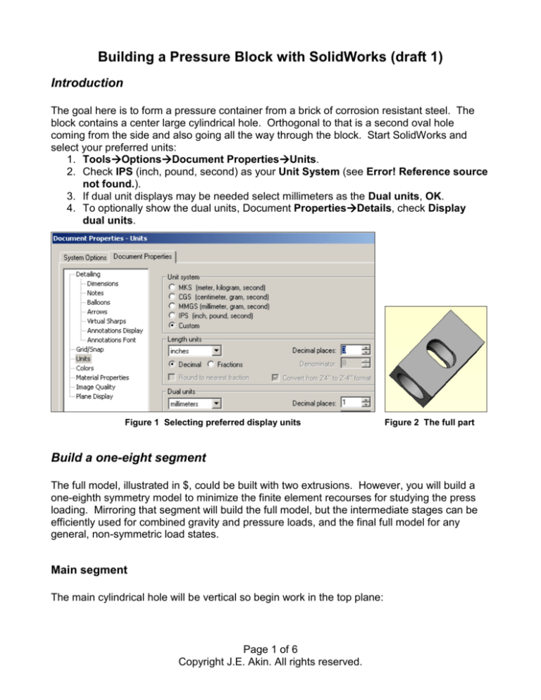
Figure 2 The full part
Build a one-eight segment
The full model, illustrated in $, could be built with two extrusions. However, you will build a
one-eighth symmetry model to minimize the finite element recourses for studying the press
loading. Mirroring that segment will build the full model, but the intermediate stages can be
efficiently used for combined gravity and pressure loads, and the final full model for any
general, non-symmetric load states.
Main segment
The main cylindrical hole will be vertical so begin work in the top plane:
Page 1 of 6
Copyright J.E. Akin. All rights reserved.
1. Right click TopInsert
sketch.
2. Insert two centerlines from the
axis origin, and then construct
a quarter circle.
3. From the bottom of the arc insert two horizontal and vertical lines to close the
segment.
4. Use the Smart dimension to set the arc to 18.75/2 inches, and the outer two
sides to 24.75/2 inches.
5. Select Extrude Boss/Base to
open the Extrude panel.
6. Select blind for Direction 1 and
D1 to 21 inches, OK (see
Error! Reference source not
found.).
Page 2 of 6
Copyright J.E. Akin. All rights reserved.
7. Verify the final shape.
Cross passage
The oval intersecting passage matches the inner diameter, but has two 5 inch radius semicircular ends on a rectangular center. Build one-fourth of the area and cut it out:
1. Click on one of the rectangular walls, Insert sketch.
2. Sketch and dimension the area to be cut out.
3. Pick Extruded Cut to open the Cut-Extrude panel.
4. Select through all as the Direction 1, OK.
Verify the completed 1/8 symmetry part as summarized in Figure 3. (Rotate it by holding
down the center mouse button and move the mouse). When you are satisfied that it is
correct save this stage, using PV as short for Pressure Vessel:
1. FileSave as PV_1_8.sldprt (for pressure or thermal loading only).
2. Continue the construction process as described next.
Page 3 of 6
Copyright J.E. Akin. All rights reserved.
Figure 3 Completing the 1/8-th symmetry section
Mirror for quarter model
Continue the construction with:
1. InsertPattern/MirrorMirror to open the Mirror panel.
2. Select the small rectangular face to be the Mirror Face, open Bodies to Mirror.
3. Select the original body and preview the new shape.
4. Check Merge bodies, OK.
5. FileSave as PV_1_4.sldprt.
These steps are outlined in Figure 4. Next you generate the half body.
Page 4 of 6
Copyright J.E. Akin. All rights reserved.
Figure 4 Completing the 1/4-th symmetry body
.
Mirror for half model and full model
Continue this approach:
1. Mirror and merge using either of the flat center planes, as in Figure 5.
2. FileSave as PV_1_2.sldprt for pressure and gravity loading.
That gives the half model. One more repeat finishes the initial part:
1. Again, Mirror and merge using either of the flat long rectangular planes illustrated in
Figure 6.
2. FileSave as PV_1_1.sldprt for arbitrary loadings.
Now any of the saved part stages can be used to minimize the CosmosWorks resources, and
engineer’s time. The choice will, of course, depend on the load conditions. (Look for a
similarly named CosmosWorks demonstration.)
Page 5 of 6
Copyright J.E. Akin. All rights reserved.
Figure 5 Mirror again for half the part.
Figure 6 Completing the part with another mirror operation
Page 6 of 6
Copyright J.E. Akin. All rights reserved.


