Applied Mechanics and Materials Vols. 789-790 (2015) pp 1176-1180
© (2015) Trans Tech Publications, Switzerland
doi:10.4028/www.scientific.net/AMM.789-790.1176
Submitted: 2015-05-17
Accepted: 2015-05-27
Online: 2015-09-02
Performance of Grouted Splice Sleeves with Tapered Bars
Under Axial Tension
Ahmad Baharuddin Abd Rahman1,a*, Loh Hsi Yoon1,b, Izni Shahrizal Ibrahim1,c,
Roslli Noor Mohamed1,d, Shahrin Mohammad1,e and A Aziz Saim1,f
1
Faculty of Civil Engineering, Universiti Teknologi Malaysia, 81310 Skudai, Johor, Malaysia
a
baharfka@utm.my, bhsiyoon@hotmail.com, ciznisyahrizal@utm.my, droslli@utm.my,
e
shahrin@utm.my and faaziz@utm.my
Keywords: splice sleeve, anchorage bond, grouted sleeve, precast concrete connection
Abstract. Many structural failures in precast concrete buildings are initiated by connection failures.
To avoid such failures, the connections should have enough strength to join the reinforcement bars
between precast concrete panels. This paper presents the structural performance and behaviour of a
proposed splice sleeve connection using generic steel pipe. The connection consisted of steel bars
with tapered nuts confined in grouted steel pipes. The connections were subjected to increasing
axial tension until failure. The results show that the use of smaller pipes gives better confinement
effects and provide higher bond strength. A short embedment length of about 10 times rebar
diameter is able to provide full tensile strength of the connected rebars. As compared to long
embedment length of conventional lapping of steel bars, the proposed connection is able to provide
structural continuity with short embedment length.
Introduction
Prefabricated precast concrete components contribute to sustainable practices in terms of
integrated design, effective use of materials, less construction waste and less site disturbance. The
success of precast construction in terms of speed and stability relies mainly on the structural
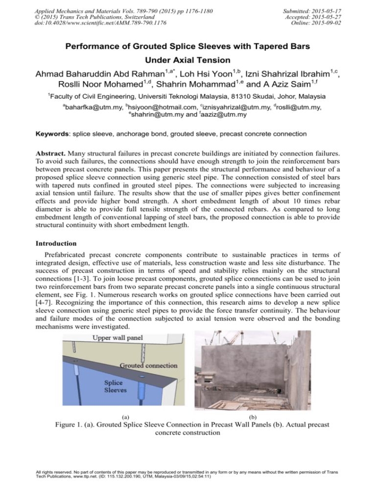
connections [1-3]. To join loose precast components, grouted splice connections can be used to join
two reinforcement bars from two separate precast concrete panels into a single continuous structural
element, see Fig. 1. Numerous research works on grouted splice connections have been carried out
[4-7]. Recognizing the importance of this connection, this research aims to develop a new splice
sleeve connection using generic steel pipes to provide the force transfer continuity. The behaviour
and failure modes of the connection subjected to axial tension were observed and the bonding
mechanisms were investigated.
(a)
(b)
Figure 1. (a). Grouted Splice Sleeve Connection in Precast Wall Panels (b). Actual precast
concrete construction
All rights reserved. No part of contents of this paper may be reproduced or transmitted in any form or by any means without the written permission of Trans
Tech Publications, www.ttp.net. (ID: 115.132.200.190, UTM, Malaysia-03/09/15,02:54:11)
Applied Mechanics and Materials Vols. 789-790
1177
Experimental Programs
The research comprised experimental tests on 16 splice specimens made from ordinary steel
pipes as the sleeves, see Fig. 2. The steel pipe was used to join two discontinuous reinforcement
bars by grouting. Each of the reinforcement bar to be connected has a special cone-shaped ‘nut’
complete with thread at the connected end.
Two sizes of steel pipe in grade S275 were used; 78.9 mm inner diameter with 5 mm thick and
65 mm inner diameter with 4 mm thick. The grout used for joining the steel rebars was Sika Grout
215. The compressive strengths of grout after 7 days are shown in Table 1. The size of the
connected steel rebars was 20 mm diameter deformed bars with an average tensile strength of 219
kN. The specimens were categorized into: (1). N series: consisted of 78.9 mm inner diameter 5mm
thick steel pipes with different pipe length, grout strength, tapered nuts, and internal pipe surface
condition. (2) T series: consisted of 65 mm inner diameter 4 mm thick steel pipes with different
tapered nuts and internal pipe surface condition.
N series was selected to study the effect of tapered nuts and its inclination angle, infill material,
pipe length, and also the internal surface conditions to the performance of the connection.
Meanwhile, T series was selected to further improve and verify the performance of the connection.
The bond between the pipe and grout is an important factor in developing a successful grouted
connection [4, 5], hence, several specimens with different design models were cast and tested in
attempts to develop a successful connection. A successful connection is defined as a connection that
can cause the connected steel bars to fracture outside the splice sleeve. In the first attempt, model
M1 was done by incorporating two steel rings cut from a smaller diameter pipe and welded to the
inside of the pipe at both ends. Another model, M2 was done by applying just a ring of weld
material around the inner face of the pipe. These rings act as the ridges or shear keys, see Fig. 2.
Embedded length
Grout
Steel pipe
(a). Splice connection
(b) 150
(c) 300
(d) 450
Figure 2. Grouted splice connection using steel pipe with different tapered nuts
The main parameters investigated were: (1) Pipe diameter: N - 78.9 mm inner diameter, T 65mm inner diameter, (2) Nut inclination angle: 15o, 30o, 45o and 0o (this represents a bare bar
without an attached tapered nut), (3) Pipe length: 300 mm, 400 mm, 500 mm, (4) Pipe inner surface
condition: O – pipe with smooth surface and without any ridges; M – pipe with ridges as the shear
keys in the inner surface of the pipe.
The specimens were named according to these variables in sequence. e. g. NK15-400-O: (N)
78.9 mm ID pipe, (K) Sika grout, (15) nuts with inclination angle of 15o, (400) 400 mm in pipe
length and (O) smooth surface pipe.
1178
Manufacturing Science and Technology VI
Results and Discussions
Tensile tests were first carried out to determine the tensile strength of the grouted sleeve
connections. Referring to Fig. 3, three connection failure modes were observed; 1: Bond failure
between grout-to-rebar, 2: Bond failure between grout-to-sleeve and 3: Rebar fracture. The
corresponding failure load, bond stresses are shown in Table 1. Failure mode 3, where the rebar
fractured outside the sleeve, is the preferred one as the splice connection is able to provide full
tensile strength of the connected rebars.
1
2
3
Figure 3. Failure modes of connection; 1: Grout-to- rebar bond failure, 2: Grout-to-sleeve bond
failure and 3: Bar fracture
Table 1: Ultimate load of splice connection
Influence of Nuts
It is seen in specimens 1, 2 and 3 that by using a bare bar without tapered nuts, the connections
failed due to bar pullout, which was caused by the failure of the bond between grout and bar. By
incorporating tapered nuts as seen is specimens 4 to 8, the failure occurred due to bond failure
between the grout-to-pipe interface, indicating that the bond between rebar-to-grout had increased
due to the presence of tapered nut. However, the higher the inclination angle of nut, the lower the
ultimate load it can sustain. Then, by adding ridges or shear keys to the internal pipes, as seen in
Applied Mechanics and Materials Vols. 789-790
1179
specimens 9 to 11, the bond between the grout and the pipe improved significantly to the extent that
the connected rebars failed by fracture.
Influence of Pipe Diameter
The T-series specimens used a smaller pipe of 65 mm inner diameter as compared to N-series
with 78.9 mm inner diameter. A smaller pipe gives better confinement effects and thus results in
higher bond strength. It is seen, the new configuration results in bar tensile failures as opposed to
failure by bar pull-out. However, T-series specimens 15 and 16 give lower ultimate load in
comparison to the N-series specimens 6 and 11 results respectively due to low grout compressive
strength.
Influence of Grout
As mentioned above, the low compressive strength of grout in specimens 15 and 16 affects the
the ultimate strength of the connections. Therefore, the strength of grout is also an important factor
in determining the performance of the connection.
Stress-strain Relationships
Three specimens in T-series were mounted with strain gauges to measure longitudinal and
tangential strains in the pipe as well as axial strains in the bars. Fig. 4 shows the stress-strain curve
for the reinforcing bars. Both specimens 13 and 14 showed bar fracture failure. As for specimen
TK45-400-O, the specimen fails in bond between the grout and pipe. Therefore the axial strains in
the pipe are generally very small.
Specimen 14
Specimen 13
Specimen 15
(a) Specimens 13 and 14
(b) Specimen 15
Figure 4. Stress-strain curve of reinforcing bars
Fig. 5 shows the relationships between the stress in the bar versus the tangential and longitudinal
strains in the pipe for all three specimens. All three longitudinal strain gauges show linearly
increasing tension strains against applied stresses. The tangential strain values deserve special
attention. TK30-400-M and TK45-400-M exhibit almost similar trend of stress-tangential strain
curves. Tangential strain gauges indicate compression strain initially and then reverse where the
pipes experience expansion. For specimen TK45-400-O, compressive strain continues until the
specimen fails in bond. It is believed that the pull-out force that is applied to the bar causes the
grout to be pulled out together with the bar, allowing the pipe to reverse back to its original state.
Due to the smooth inner surface of the specimen pipe, TK45-400-O, poor bonding causes the grout
to eventually slip out. By having ridges on both ends of the pipe, as in the case of specimens
TK30-400-M and TK45-400-M, the motion of the grout is impeded and results in a radial expansion
of the pipes until the bars reach their ultimate tensile strength. The tangential strain results show
that the pipe undergoes compression at initial loading and the pipe expands as the loading increases
until the bar ultimate strength is reached.
1180
Manufacturing Science and Technology VI
Tangential strain
TK30-M
Longitudinal strain
TK45-M
TK30-M
TK45-M
TK45-O
TK45-O
Figure 5. Stress in the bar versus strains in the pipe
Conclusions
The results of this study show that the splice connection using steel pipe is feasible as it allows
continuity between two connected rebars. Further conclusions are as follows:
1. The use of nuts changes the failure mode of bond failure between grout and bar to a bond
failure between grout and pipe.
2. Shear keys by means of weld ring or steel plate at both pipe ends prevents the bar and grout
slippage and subsequently mobilizes the grout confining action resulting in high bond strength,
and then causes the connected steel bar to fracture outside the sleeve.
3. A grouted connection using steel pipe with shear keys, steel bar embedment length of 190 mm
(about 10 bar diameter) with tapered angle is able to provide the full tensile strength of the
connected rebars.
4. The compressive strength of grout plays a very important role in this type of connection as it
serves as a medium to transfer the force from one bar to another.
Acknowledgement
The authors would like to thank the Universiti Teknologi Malaysia (UTM) and Ministry of Higher
Education (MOHE) – Vot 4L009, in conducting this experimental study.
References
[1]
[2]
[3]
[4]
[5]
[6]
[7]
ACI Committee 550, ACI 550.1R-01 report, Emulating cast-in-place detailing in precast
concrete structures, 2001.
A. Einea, T. Yamane, M.K. Tadros, Grout-filled pipe splices for precast concrete construction,
PCI Journal, January – February, 1995, pp. 82-93.
A.B. Abd Rahman, J.H. Ling, Z. Abd Hamid, et al, Development of splice connections for
precast concrete structures, Advanced Materials Research, 2014, 980:132-136.
M.J. Ameli, J.E. Parks, D.N. Brown and C. P. Pantelides, Seismic evaluation of grouted splice
sleeve connections for reinforced precast concrete column-to-cap beam joints in accelerated
bridge construction, PCI Journal, March – April, 2015, pp. 80-103.
E. Enin and G. Morcous, Non-proprietary bar splice sleeve for precast concrete construction,
Engineering Structures, 2015, 83: pp. 154-162.
S.J. Aldin Hosseinl and A.B. Abd. Rahman, Analysis of spiral reinforcement in grouted pipe
splice connectors, Gradjevinar. 2013, 65(6):537-546.
A.A. Sayadi, A.B. Abd. Rahman, M. Z. Bin Jumaat, et al, The relationship between
interlocking mechanism and bond strength in elastic and inelastic segment of splice sleeve,
Construction and Building Materials. 2014, 55: pp. 227-237.
Manufacturing Science and Technology VI
10.4028/www.scientific.net/AMM.789-790
Performance of Grouted Splice Sleeves with Tapered Bars under Axial Tension
10.4028/www.scientific.net/AMM.789-790.1176


