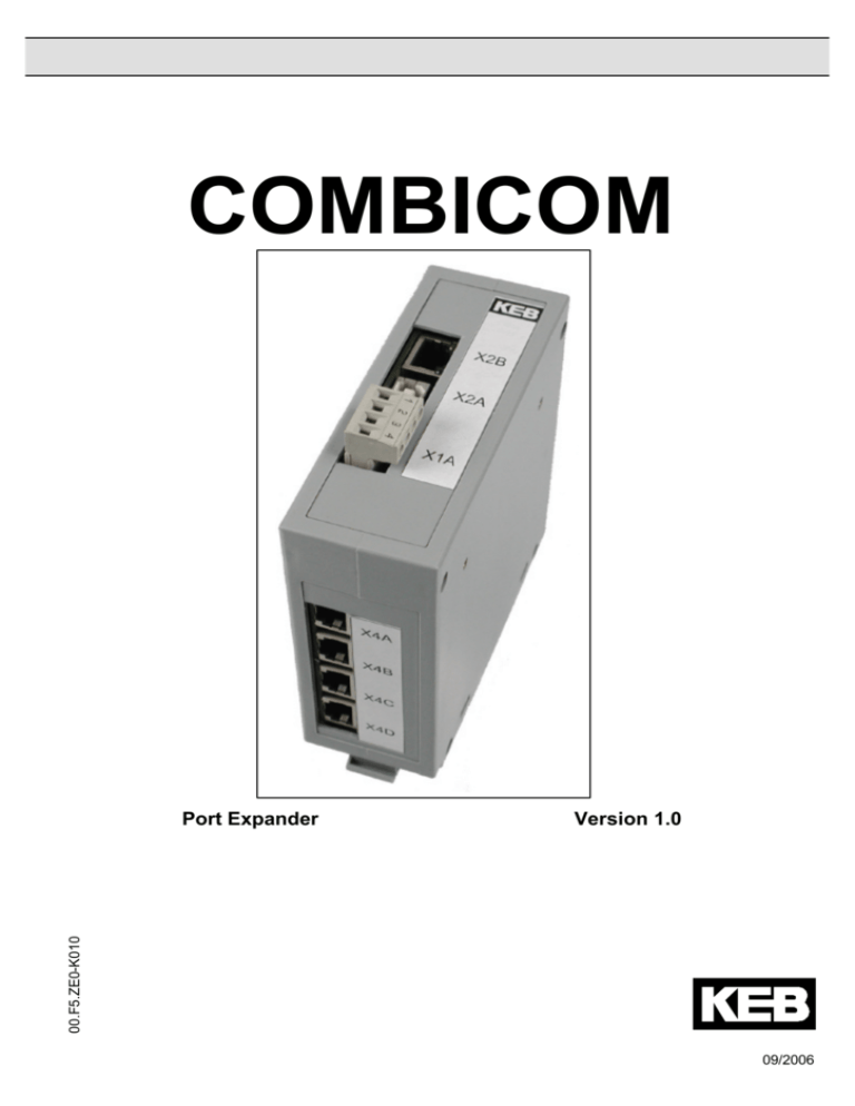
COMBICOM
Version 1.0
00.F5.ZE0-K010
Port Expander
09/2006
Port Expander
1 General Information ................................................................................. 3
1.1 Product description ................................................................................................ 3
1.2 Technical Data......................................................................................................... 3
1.3 Accessories ............................................................................................................. 3
2 Voltage supply.......................................................................................... 3
3 Ethernet interface..................................................................................... 4
3.1
3.2
3.3
3.4
3.5
3.6
3.7
3.8
Supported protocols ............................................................................................... 4
IP Address ............................................................................................................... 4
DHCP Server............................................................................................................ 4
DIN66019II Port........................................................................................................ 4
Modbus Port ............................................................................................................ 5
Http Port................................................................................................................... 5
Node addressing ..................................................................................................... 5
Data port password................................................................................................. 5
4 USB interface............................................................................................ 6
5 HSP5/485 Ports......................................................................................... 6
5.1 Port 4 Mode.............................................................................................................. 6
6 Internal Parameters.................................................................................. 7
6.1
6.2
6.3
6.4
6.5
6.6
6.7
System Parameters................................................................................................. 7
Operation Parameter............................................................................................... 7
Ethernet Parameter ................................................................................................. 8
Userdefinition parameter........................................................................................ 9
Debugging ............................................................................................................... 9
Position of the connectors/diagnostic displays ................................................. 10
Terminal assignments .......................................................................................... 10
2
Port Expander
1 General Information
The presented documentation as well as the herein mentioned hard and software are developments of Karl E.
Brinkmann GmbH. Errors excepted. The company Karl E. Brinkmann GmbH established this documentation
to the best of her knowledge but without engagement, that the herein stated specifications may not provide
the user with the expected advantages. The Karl E. Brinkmann GmbH reserves the right to change the
specifications without prior notification or further obligation. All rights reserved.
This instruction manual describes the software state as of 09/2006.
1.1
Product description
This manual describes a communication gateway with Ethernet and USB interface and 4 HSP5/485 interfaces
for the connection to frequency inverters or KEB COMBIVERT F5 operators. Voltage supply is made via an
external 24V power supply unit or by the USB cable. The Port Expander can be placed remotely on a
mounting rail in the control cabinet or locally on the table. The last HSP5/485 interface can be switched
alternatively also to the DIN66019II protocol.
1.2
Technical Data
Voltage supply X1A
USB interface X2A
Ethernet interface X2B
HSP5/485 interfaces X4
Housing
Operation temperature
Part number
1.3
12..30VDC±0%, 2,4W max. (12V/0,2A 24V/0,1A)
USB 2.0, type B socket, current consumption 0,4A max.
RJ45, IEEE 802.3 10/100Base-TX
RJ45, max. line length 100m
118 x 140 x 45 mm
-10° to 45° C
00.F5.025-0080
Accessories
USB cable plug A-B 1,0m
CAT5 cable 2*RJ45 2,0m yellow
Operator HSP5/485, RJ45 connection
Converter cable RJ45 – HSP5 DSUB9, 2,5m
Adapter DSub9/Western
00.F5.0C4-1010
00.F5.0C3-1020
00.F5.060-9002
00.F5.0C0-4025
00.F5.0C0-0002
2 Voltage supply
No further voltage supply is necessary if the unit is operated by the USB interface. 24 volt are supplied via
terminals X1A.1 (-) and X1A.2 (+) if the port expander is placed in a control cabinet. Terminal X1A.4 serves
against interferences on the cable shield and shall be connected with the grounded mounting rail/control
cabinet rear-panel via a short cable.
3
Port Expander
3 Ethernet interface
The Ethernet interface recognizes automatically the used speed (10 or 100 MBaud), half or full duplex
operation, polarity as well as MDI/MDIX operation (auto-crossover). This parameters may be set also
manually. Patch or crossover cables can be used. Always recommended is a category 5 shielded network
cable with 8 pole RJ45 connector
3.1
Supported protocols
ARP
ICMP
TCP/IP
TCP/UDP
DHCP
Address Resolution Protocol Response
Echo Response (Ping)
DIN66019II, Modbus/TCP, Http
DIN66019II, Modbus/TCP
BootP Response, can be switched off
30 simultaneous connections (sockets) are max. available via the Ethernet interface. These connections are
created automatically in case of new inquiries via TCP and UDP and automatically closed after approx. 30
seconds without data transfer. Further inquiries are ignored if the maximum number is reached.
3.2
IP Address
The IP address is adjusted in parameter ET.01. In case of doubt the address to be adjusted
is given by the network administrator, because it is not allowed to have double addresses in the entire
connected Ethernet. When using a direct connection of a port expander and PC by means of a patch cable,
this IP address should be adjusted in such way that the difference is only in the lowest byte to the address of
the PC (same network but differend node). With activated DHCP server the port expander answers
BootP/DHCP-Requests and enables the connected PC to receive a temporary valid IP address (see section
DHCP server).
3.3
DHCP Server
The DHCP server functionality is activated / deactivated with parameter ET.13. BootP- and DHCP requests
are answered delayed in activated state. The following restrictions become valid because the port expander
has no information about available IP addresses in the network:
The DHCP server is only provided for operation with cross/patch cable to a PC/notebook, in order to assign an
IP address to the PC/notebook if neccessary. Thus an end to end operation without manual intervention and
without knowledge of the IP protocol is possible.
All requests are collected and if 3 equal requests are recognized, an appropriate response is transmitted.
Thus in standard network operation the standard DHCP servers can assign a valid IP address first (before the
port expander assigns it).
The IP address of the port expander increased by 1 is preset as IP address. The IP address of the port
expander decreased by 1 is preset, if the low byte of the IP address is higher than 254.
3.4
DIN66019II Port
This port is used for the transmission of inverter parameter data by means of enclosed DIN66019II/IP
telegrams. Several simultaneous connections of different clients are possible on this port. As a standard the
port is set to 8000. The adjustment can be changed with parameter ET.02. In order to make several
simultaneous connections from one client to different inverters, the following 3 port numbers (8001..8003) are
available with same protocol. Available are TCP/IP and TCP/UDP connections. Access can occur also with
the COMBIVIS5 IP driver. The slave address in the DIN66019II protocol serves as node address (see section
node addressing). The DIN66019II port can be protected with the data port password (see section data port
password). Attention: This port numbers must not overlap with the Modbus port !
4
Port Expander
3.5
Modbus Port
This port is used for data transmission with the Modbus/TCP protocol. Several simultaneous connections of
different clients are possible on this port. As a standard the port is set to 502. The adjustment can be changed
with parameter ET.03. Attention: This port must not overlap with the DIN66019II ports! TCP/IP and also
TCP/UDP connections are available here.
The desired parameter address is specified as Modbus register address. The Modbus unit identifier specifies
the node address (see section node addressing). All accesses are made with indirect set addressing.
The Modbus functions 3 and 4 enable reading of 16 bit parameter values. Only a Modbus register count of 1 is
supported. Function 6 serves for writing of a 16 bit parameter value. The DIN66019II port can be protected
with the data port password (see section data port password).
The Modbus protocol doesn´t offer a direct access to 32 bit data. So at LONG parameters only the lower word
is readable. The 16 bit value is sign-extended to 32 bit during writing.
3.6
Http Port
On the standard HTTP port 80 the status page can be called up via a browser. This status page contains
informations about the version of the unit as well as the current adjusted IP port numbers for DIN66019II and
Modbus.
3.7
Node addressing
Access to parameters with the protocols DIN66019II and Modbus occurs node-dependent, i.e. 5 node
addresses are available. The basis node address can be adjusted via parameter SY.06.
If SY.06 is set to 0 (default value), node 0 has access to internal parameters in the port expander, nodes 1..4
have access to HSP5/485 ports 1..4. All other node addresses are rejected with error code unit not ready`
(exception: Port 4 is in DIN66019II mode, see below.). These 5 node addresses can be shifted upwards with
parameter SY.06. This enables e.g. COMBIVIS that the port expander can be operated among other units in a
project.
3.8
Data port password
In order to protect the Ethernet interface against unauthorized write accesses, a writing protection password
can be defined with parameter ET.09. Read accesses are always possible. The definition of the password can
be made only via USB interface. Value 0 switches off the write protection. On access via Ethernet this
password must be entered once in parameter ET.09 in order to execute any write operations. If the password
is not correctly entered, the error message operation not possible and/or Modbus exception code 1 is
displayed at next writing. The port expander cancelles the IP connection automatically and the password must
be entered again, if the connection is released via TCP or communication is suspended for 30 seconds.
ATTENTION: Read out of CFG files via Ethernet interface is not possible with activated data port password,
because pointer parameters must be also written here.
5
Port Expander
4 USB interface
Attention: The use of the USB-interface with PCs / Notebooks is designated only for temporary operation. A
permanent connection for all-time use in industrial environment is not recommended because of the limited
interference immunity of USB.
The USB interface connects the port expander via a commercial USB cable with a PC or a USB-hub.
DIN66019II is used as protocol. Access to internal parameters as well as to the HSP5/485 ports is possible
(see section node addressing). The port expander can be power-supplied also via the USB interface. A virtual
COM port driver (VCP) is necessary on PC side which provides when installed once a further COM interface
to communication with COMBIVIS or other applications. The interface parameters baud rate, character format
or parity are not important, because the quickest possible transmission method is used here. If KEB drivers
are used, the adjustment "send single" should be switched off.
5 HSP5/485 Ports
The port expander has four HSP5/485 interfaces, which allows simultaneous communication with up to 4
Combivert F5 inverters or operators. The protocol is HSP5 in interference-proof RS485 construction. Line
lengths up to 100 meters are possible here.
Connection to an inverter occurs via standard CAT5 cable with RJ45 plug on both sides and 00.F5.060-9002
operator.
Connection to the diagnostic interface of a F5 operator occurs via special converter cable 00.F5.0C0-4xxx as
well as the adapter DSub9/Western 00.F5.0C0-0002.
The transmission rate of each port can be adjusted to a fixed value or an automatic recognition/adaption with
parameters UD.04..UD.07. Parameters RU.01..RU.04 display the current value of the port. The connection is
monitored by reading and if necessary by correcting during automatic recognition/adaption. Parameter UD.03
sets the maximum time for waiting for an answer.
5.1
Port 4 Mode
Port 4 can be changed to DIN66019II mode with parameter UD.08. Then a serial RS485 connection to several
units can be generated here which recognize the DIN66019II protocol.
A 2-wire connection is not possible by hardware limitations. All node addresses from 4 to 239 are processed
with this port (at basis node address SY.06 = 0). An automatic transmission rate recognition is not possible
here any longer moreover the port 4 baud rate must be adjusted manually to the correct value of the
connected units.
A RS485 adapter cable for the connection to KEB operators has the following assignment:
X4D.1 --- DSub9.4
X4D.2 --- DSub9.5
X4D.4 --- DSub9.8
X4D.5 --- DSub9.9
X4D.3 --- DSub9.7
6
Port Expander
6 Internal Parameters
6.1
System Parameters
sy.01
software date
This parameter displays the date of the installed firmware.
Address 0001h
sy.02
device identifier
Address 0002h
This parameter displays the software-identification number (CFG-ID) for COMBIVIS.
sy.04
cfg. data sel.
Selection of internal device data.
Address 0004h
sy.05
cfg. data
Output of internal device data.
Address 0005h
sy.06
node address offset
Address 0006h
This parameter defines the adjustment of the node address. See section node addressing
sy.10
other
Display of unit type group for COMBIVIS.
6.2
Address 000Ah
Operation Parameter
ru.01
port 1 actual baud rate
ru.02
port 2 actual baud rate
ru.03
port 3 actual baud rate
ru.04
port 4 actual baud rate
Displays the actual baud rate of the HSP5/485 ports 1 to 4.
Address 0201h
Address 0202h
Address 0203h
Address 0204h
ru.05
port 1 timeout counter
Address 0205h
ru.06
port 2 timeout counter
Address 0206h
ru.07
port 3 timeout counter
Address 0207h
ru.08
port 4 timeout counter
Address 0208h
Displays the error counter status of HSP5/485 ports 1 to 4. These parameters can be reset by
writing. The error counter is increased each time, if an inquiry was not answered on the
corresponding port (Timeout).
7
Port Expander
6.3
Ethernet Parameter
et.00
MAC address
Address 0300h
The MAC address (Media Access Control) is formed of 6 byte. The first three bytes contain the
manufacturer's code (00-08-FA). Only the lowest 4 bytes „FAxxxxxx„ are displayed here. This
address is assigned by the manufacturer and cannot be changed.
et.01
IP address
Address 0301h
The IP address consists of 4 bytes and is the unique identification of one Internet participant. In case
of doubt the network administrator gives the address to be adjusted.
et.02
DIN66019II port number
Address 0302h
This parameter adjusts the port number for the access via DIN66019II/TCP protocol. The following 3
port numbers are also available.
et.03
MODBUS port number
Address 0303h
This parameter adjusts the port number for the access via Modbus/TCP protocol. The standard value
is 502.
et.04
IP error count
Serves for the diagnosis of the IP protocol stack.
Address 0304h
et.05
TCP connections
This parameter displays the number of active TCP connections.
Address 0305h
et.06
UDP connections
This parameter displays the number of active UDP connections.
Address 0306h
et.08
TCP multicount
This parameter serves only for diagnostic purposes.
Address 0308h
et.09
data port password
Address 0309h
This parameter defines the write protection password for the data port. The programming of the
password occurs only via the USB interface. Then this password must be entered again for write
access via the data port. Error message "operation not possible" is returned in case of locked data
port write access. Value 0 switches off the write protection password.
et.12
data port response delay
Address 030Ch
Displays the response delay time for the Ethernet data ports in ms. The network trafic can be
decreased if higher values are adjusted. Value 0 enables the fastest communication with the port
expander, however a high network trafic is also produced.
et.13
DHCP server active
Address 030Dh
Serves for switching off and on of the DHCP server functionality. See section DHCP server.
et.14
link state
Displays status information for the Ethernet connection
Address 030Eh
et.15
link mode
Address 030Fh
Specifies the settings of the ethernet interface. Her fixed values or autodetection can be selected.
The additional clearlock value of 32 activates a special behavior where link problems on
autodetection on both sides (Port Expander and Switch) is solved automatically.
8
Port Expander
6.4
Userdefinition parameter
ud.01
password
Address 0801h
Password input for the corresponding user level. The following values for the password level are
possible:
200
User write protection (operating parameter cannot be changed)
440
User reading/writing
ud.03
port timeout
Address 0803h
Sets the timeout value for all ports. Too small values lead to communication problems. The default
value of 50ms is appropriate for most applications. After expiration of this time without answer a
telegram with error code 1 (Device not ready) is returned.
ud.04
port 1 baud rate
Address 0804h
ud.05
port 2 baud rate
Address 0805h
ud.06
port 3 baud rate
Address 0806h
ud.07
port 4 baud rate
Address 0807h
Adjusts the used baud rate of the HSP5/485 ports 1 to 4. Value 12: autodetect is searching for the
baud rate of the connected unit and adjusts itself if possible. Value 13:auto maximum is also
searching for the baud rate of the connected unit and the highest possible value is adjusted (not
when connection via operator). The following values are assigned to the baud rates: 3 – 9600, 4 –
19200, 5 – 38400, 6 – 55500, 8 – 100000, 10 – 125000, 11 - 250000
ud.08
port 4 DIN66019II mode
Address 0808h
Changes port 4 to 66019II operating mode (1). This special operating mode is switched off at value 0.
ud.09
indirect set pointer
Address 0809h
Display and adjustment of the set selector for indirect parameter access.
ud.10
active set
Display and adjustment of the active set.
Address 80Ah
ud.11
serial no. (date)
Address 080Bh
ud.12
serial no. (count)
Address 080Ch
ud.13
QS number
Address 080Dh
Display of the factory-made serial number with additional information
6.5
Debugging
Db.00..04
dbg xxx
Only for internal diagnostics. No function for the user.
Address 06xxh
9
Port Expander
6.6
Position of the connectors/diagnostic displays
SPEED (yellow, above in X2B)
On: 100MBd link recognized
X2B Ethernet interface
LINK/ACTIVE (green, below in X2B)
Off: no link
On: link is available
Blinking: data receive
X2A USB interface
POWER/COM (yellow, right)
Off: no voltage supply
On: voltage supply OK
Blinking: Parameter access active
WINK (yellow, left)
Signals IP scan requests
X1A voltage supply/shield
X4A..D (bottom side)
HSP5/485 Ports 1..4
6.7
Terminal assignments
X1A Power (plug)
1
0V in
2
+24V in
3
Shielding/PE
4
Shielding/PE
X2A USB (Type B receptacle)
1
+5V in
2
Usb3
Usb+
4
GND
X2B Ethernet (RJ45 female)
1
TXD+
2
TXD3
RXD+
4
n.c.
5
6
7
8
X4A..D HSP5/485 Ports (RJ45 female)
1
TXD+
5
2
TXD6
3
GND
7
4
RXD+
8
n.c.
RXDn.c.
n.c.
RJ45 Socket (Top View)
1
8
RXDGND
EnTx+
EnTx10
Port Expander
Karl E. Brinkmann GmbH
Försterweg 36-38 •D-32683 Barntrup
fon: +49 5263 401-0 • fax: +49 5263 401-116
net: www.keb.de • mail: info@keb.de
KEB Antriebstechnik GmbH & Co. KG
Wildbacher Str. 5 •D–08289 Schneeberg
fon: +49 3772 67-0 • fax: +49 3772 67-281
mail: info@keb-combidrive.de
KEB Italia S.r.l.
Via Newton, 2 •I-20019 Settimo Milanese (Milano)
fon: +39 02 33500782 • fax: +39 02 33500790
net: www.keb.it • mail: kebitalia@keb.it
KEB Antriebstechnik Austria GmbH
Ritzstraße 8 •A-4614 Marchtrenk
fon: +43 7243 53586-0 • fax: +43 7243 53586-21
Kostelni 32/1226 •CZ-370 04 Ceské Budejovice
fon: +420 38 7319223 • fax: +420 38 7330697
net: www. keb.at • mail: info@keb.at
KEB - YAMAKYU Ltd.
15–16, 2–Chome, Takanawa Minato-ku
J–Tokyo 108-0074
fon: +81 33 445-8515 • fax: +81 33 445-8215
mail: info@keb.jp
KEB CHINA Karl E. Brinkmann GmbH
(Xinmao Building, Caohejing Development Zone)
No. 99 Tianzhou Road (No.9 building, Room 708)
CHN-200233 Shanghai, PR. China
fon: +86 21 54503230-3232 • fax: +86 21 54450115
net: www.keb.cn • mail: info@keb.cn
KEB CHINA Karl E. Brinkmann GmbH
No. 36 Xiaoyun Road • Chaoyang District
CHN-10027 Beijing, PR. China
fon: +86 10 84475815 + 819 • fax: +86 10 84475868
net: www.keb.cn • mail: hotline@keb.cn
KEB Antriebstechnik Austria GmbH
Organizacni slozka
Kostelni 32/1226
CZ-370 04 Ceske Budejovice
fon: +420 38 7699111 • fax: +420 38 7699119
mail: info.keb@seznam.cz
KEB España
C/ Mitjer, Nave 8 - Pol. Ind. LA MASIA
E-08798 Sant Cugat Sesgarrigues (Barcelona)
fon: +34 93 897 0268 • fax: +34 93 899 2035
mail: vb.espana@keb.de
Société Française KEB
Z.I. de la Croix St. Nicolas • 14, rue Gustave Eiffel
F-94510 LA QUEUE EN BRIE
fon: +33 1 49620101 • fax: +33 1 45767495
net: www.keb.fr • mail: info@keb.fr
KEB (UK) Ltd.
6 Chieftain Buisiness Park, Morris Close
Park Farm, WellingboroughGB-Northants, NN8 6 XF
fon: +44 1933 402220 • fax: +44 1933 400724
net: www.keb-uk.co.uk • mail: info@keb-uk.co.uk
KEB Polska
ul. Budapesztanska 3/16 •PL–80-288 Gdansk
fon: +48 58 524 0518 • fax: +48 58 524 0519
mail: vb.polska@keb.de
KEB Taiwan Ltd.
No.8, Lane 89, Sec.3; Taichung Kang Rd.
R.O.C.-Taichung City / Taiwan
fon: +886 4 23506488 • fax: +886 4 23501403
mail: info@keb.com.tw
KEB Korea Seoul
Room 1709, 415 Missy 2000
725 Su Seo Dong, Gang Nam Gu
ROK-135-757 Seoul/South Korea
fon: +82 2 6253 6771 • fax: +82 2 6253 6770
mail: vb.korea@keb.de
KEB Sverige
Box 265 (Bergavägen 19)
S-43093 Hälsö
fon: +46 31 961520 • fax: +46 31 961124
mail: vb.schweden@keb.de
KEB America, Inc.
5100 Valley Industrial Blvd. South
USA-Shakopee, MN 55379
fon: +1 952 224-1400 • fax: +1 952 224-1499
net: www.kebamerica.com • mail: info@kebamerica.com
© KEB 00.F5.ZE0-K010 09/2006
KEB Antriebstechnik
Herenveld 2 •B-9500 Geraadsbergen
fon: +32 5443 7860 • fax: +32 5443 7898
mail: vb.belgien@keb.de
11


