Digital Tx - Department of Computer Engineering
advertisement
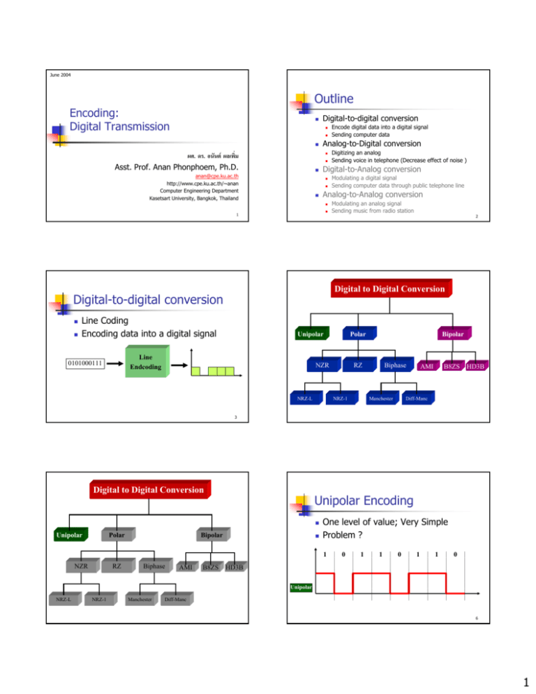
June 2004 Outline Encoding: Digital Transmission Digital-to-digital conversion ผศ. ดร. อนันต ผลเพิ่ม Asst. Prof. Anan Phonphoem, Ph.D. Analog-to-Digital conversion anan@cpe.ku.ac.th http://www.cpe.ku.ac.th/~anan Computer Engineering Department Kasetsart University, Bangkok, Thailand Line Coding Encoding data into a digital signal Unipolar Line Endcoding 0101000111 Modulating an analog signal Sending music from radio station 2 Digital to Digital Conversion Digital-to-digital conversion Modulating a digital signal Sending computer data through public telephone line Analog-to-Analog conversion 1 Digitizing an analog Sending voice in telephone (Decrease effect of noise ) Digital-to-Analog conversion Encode digital data into a digital signal Sending computer data Polar NZR NRZ-L Bipolar RZ NRZ-1 Biphase Manchester AMI B8ZS HD3B Diff-Manc 3 Digital to Digital Conversion Unipolar Encoding Unipolar Polar Bipolar One level of value; Very Simple Problem ? 1 NZR RZ Biphase AMI B8ZS 0 1 1 0 1 1 0 HD3B Unipolar NRZ-L NRZ-1 Manchester Diff-Manc 6 1 General Problems of Digital-to-digital encoding General Problems of Digital-to-digital encoding Synchronization DC components Cannot pass through some system (eg. transformer) Extra energy residing on the line Beginning/ending problem (111111111) Distortion (1111 Æ 11111) Solved by separate line Self-synchronization 7 8 Digital to Digital Conversion Nonreturn to Zero-Level (NRZ-L) Unipolar Polar Two different voltages for 0 and 1 bits Bipolar NZR RZ Biphase AMI B8ZS HD3B Voltage constant during bit interval NRZ-L NRZ-1 Manchester Absence of voltage = zero Positive voltage = one Normally, Negative = one and positive = zero no transition (no return to zero voltage) Diff-Manc 10 Nonreturn to Zero Inverted Transition Nonreturn to Zero (NRZ) Low-to-high or high-to-low denotes binary 1 No Transition denotes binary 0 Constant voltage pulse for duration of bit - Long Steam of 0 or 1 - Long Steam of 0 + Syschronize @ 1 11 12 2 Polar Encoding RZ (Return to Zero) NRZ pros and cons Pros Three levels (+ - 0) - 2 signal changes per bit Æ more BW Easy to engineer Make good use of bandwidth + Synchronization Cons dc component Lack of synchronization capability Used for magnetic recording Not often used for signal transmission 13 14 Biphase - Manchester Biphase - Differential Manchester Transition in middle of each bit period Transition serves as clock and data Low-to-high represents one High-to-low represents zero Used by IEEE 802.3 Midbit transition is clocking only Transition at start of bit represents zero No transition at start of bit represents one Used by IEEE 802.5 15 16 Digital to Digital Conversion Biphase Pros and Cons Cons At least one transition per bit time and possibly two Maximum modulation rate is twice NRZ Requires more bandwidth Unipolar Pros Synchronization on mid bit transition (self clocking) No dc component Error detection Absence of expected transition Polar NZR NRZ-L RZ NRZ-1 Bipolar Biphase Manchester AMI B8ZS HD3B Diff-Manc 17 3 Bipolar Alternate Mark Invision (AMI) Bipolar With 8 Zeros Substitution (B8ZS) “1” are positive and negative alternately - Long Steam of 0 + DC component = 0 If octet of all zeros and last voltage pulse preceding was positive If octet of all zeros and last voltage pulse preceding was negative Encode as 000+-0-+ Encode as 000-+0+- Causes two violations of AMI code Unlikely to occur as a result of noise 19 20 High Density Bipolar 3 Zeros (HDB3) Bipolar (solved long stream of “0” Æ using violation) String of four zeros replaced with one or two pulses Observe the number of “1” after last violation (to be odd or even) 1 0 0 1 0 Odd 0 0 0 0 0 0 0 1 1 0 0 0 Even 0 0 0 0 1 1 0 0 B8ZS If no “1” after last violation (e.g. 0000 then 0000), assume to be even (no “1” at all) Odd+ Î 000+ Odd- Î 000Even+ Î -00Even- Î+00+ 0 HDB3 21 22 HDB3: Example1 HDB3: Example 2 Odd Even 23 24 4 Other Schemes 2B1Q 2B1Q (Two Binary, One Quaternary) MLT-3 (Multiline Tx, three Level) Four Voltage levels Each pulse represents 2 bits 25 26 MLT-3 Block Coding Similar to NRZ-I Uses 3 levels of signals (+1, 0, -1) Transition from one level to the next at the beginning of a 1 bit No Transition at the beginning of a 0 bit Improve the line coding performance Need redundancy To ensure synchronization To detect errors Steps in Transformation Division Substitution 27 28 Block Coding Substitution For 4B/5B Choose 5-bit pattern that help in 29 Synchronization Error detection 30 5 4B/5B Encoding Outline Data Code Digital-to-digital conversion Data Code Data Code 0000 11110 1000 10010 Q (Quiet) 0001 01001 1001 10011 I (Idle) 00000 11111 0010 10100 1010 10110 H (Halt) 00100 0011 10101 1011 10111 J (start delimiter) 11000 0100 01010 1100 11010 K (start delimiter) 10001 0101 01011 1101 11011 T (end delimiter) 01101 0110 01110 1110 11100 S (Set) 0111 01111 1111 11101 R (Reset) 11001 00111 Analog-to-Digital conversion Modulating a digital signal Sending computer data through public telephone line Analog-to-Analog conversion 31 Digitizing an analog Sending voice in telephone (Decrease effect of noise ) Digital-to-Analog conversion Encode digital data into a digital signal Sending computer data Modulating an analog signal Sending music from radio station 32 Step 1: Analog to Digital Encoding Pulse Amplitude Modulation(PAM) 33 Step 2: Quantized PAM Signal 34 Step 3: Quantizing Using Sign and Magnitude 35 36 6 Step 4: Pulse Code Modulation (PCM) From Analog to PCM 37 From Analog to PCM 38 Nyquist Theorem 39 40 Sampling rate Question Solution We want to digitize the human voice. What is the bit rate, assuming 8 bits per sample? The human voice normally contains frequencies from 0 to 4000 Hz. Sampling rate = 4000 x 2 = 8000 samples/s Bit rate = sampling rate x number of bits per sample = 8000 x 8 = 64,000 bps = 64 Kbps 41 7
