Simple Multichannel RC Servo Controller for Smartphones
advertisement
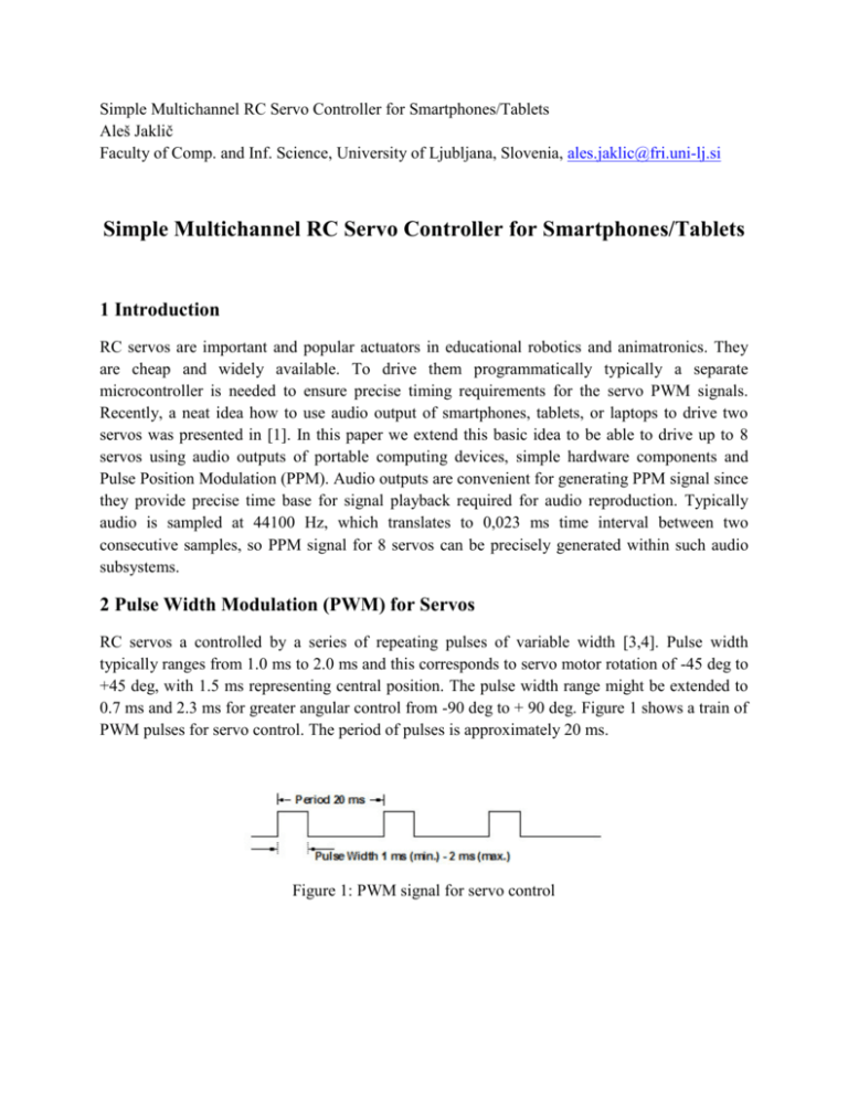
Simple Multichannel RC Servo Controller for Smartphones/Tablets Aleš Jaklič Faculty of Comp. and Inf. Science, University of Ljubljana, Slovenia, ales.jaklic@fri.uni-lj.si Simple Multichannel RC Servo Controller for Smartphones/Tablets 1 Introduction RC servos are important and popular actuators in educational robotics and animatronics. They are cheap and widely available. To drive them programmatically typically a separate microcontroller is needed to ensure precise timing requirements for the servo PWM signals. Recently, a neat idea how to use audio output of smartphones, tablets, or laptops to drive two servos was presented in [1]. In this paper we extend this basic idea to be able to drive up to 8 servos using audio outputs of portable computing devices, simple hardware components and Pulse Position Modulation (PPM). Audio outputs are convenient for generating PPM signal since they provide precise time base for signal playback required for audio reproduction. Typically audio is sampled at 44100 Hz, which translates to 0,023 ms time interval between two consecutive samples, so PPM signal for 8 servos can be precisely generated within such audio subsystems. 2 Pulse Width Modulation (PWM) for Servos RC servos a controlled by a series of repeating pulses of variable width [3,4]. Pulse width typically ranges from 1.0 ms to 2.0 ms and this corresponds to servo motor rotation of -45 deg to +45 deg, with 1.5 ms representing central position. The pulse width range might be extended to 0.7 ms and 2.3 ms for greater angular control from -90 deg to + 90 deg. Figure 1 shows a train of PWM pulses for servo control. The period of pulses is approximately 20 ms. Figure 1: PWM signal for servo control 3 Pulse Position Modulation (PPM) for Radio Control Pulse position modulation enables us to encode PWM signals of multiple servos into a single signal, that can be transmitted over radio link or in our case to be transmitted over a single audio channel. Figure 2 illustrates how 5 channels PWM pulses are encoded sequentially separated by negative pulses. Each frame of pulses is terminated by a pause or sync pulse, so that the receiver can prepare, usually resets itself, for another frame. Figure 2: Pulse Position Modulation signal frame 3 Hardware Decoder for Pulse Position Modulation Figure 3: Schematics of the hardware interface for RC Servo Controller We reused a classical design for decoding PPM signal that can decode up to 8 channels based on 5-stage Johnson counter 4017 circuit [2,5]. Figure 3 shows the schematics of the hardware interface. The input signal from the audio output of a smart device is feed into connector K1. Then it is amplified by a non-inverting operational amplifier formed by resistors R1 and R2 and IC1A. An amplified signal from pin 1 of IC1 is then fed into a comparator formed by resistors R3 an R4 and IC1B, this effectively inverts the input signal. The inverted signal is used as a CLK signal for the IC2 and also drives the reset circuit composed of resistor R5, capacitor C1 and diode D1. The IC2 outputs the demodulated servo PWM pulses on outputs Q1 to Q9 connected to connectors K2 to K10. The circuit is powered by 4 AA batteries through K11. 4 Signals in the Circuit The hardware design presents a variety of analog and digital signals suitable for observation on oscilloscope and can be used as didactic tool for oscilloscope’s use. For example a process of charging and discharging a capacitor in the reset circuit nicely illustrates how the voltage changes over time. Figure 4: Signals in the circuit Figure 4 shows the oscilloscope image of input audio signal from pin 3 of IC1A (Channel 1) and the output amplified audio signal from pin 1 of IC1A (Channel 2). The amplification 𝐴 of the non inverting operational amplifier is defined as 𝐴=1+ 𝑅2 = 26 𝑅1 The voltage divider composed of resistors R4 an R3 sets the input voltage of pin 5 of IC1B to half the VCC = 6V that is to 3V. Thus the comparator outputs voltage close to VCC if the voltage on pin 6 of IC1B is lower than 3V, and 0V if the voltage is above 3V. This effectively inverts the amplified audio input signal (See Channel 3 of Figure 4) To properly demodulate each frame, the counter IC2 4017 needs to be reset before each incoming frame. This is achieved during the pause between two consecutive frames. The voltage on RES pin 15 of IC2 is equal to the voltage on C1 that gets charged through R5 with maximal time constant τ = R5 * C1 = 15,5 ms As long the pin 7 output of IC1B goes low for a brief period of time, the capacitor C1 gets discharged through diode D1 to approximately 0.6 V, and the RES signal will not go high. When the input frame is finished the pause between frames, that is the absence of negative pulses will cause the capacitor to charge and the voltage signal RES to reach sufficient level to reset the counter IC2, thus preparing the state of the counter for the next frame. Figure 5: Signals in the circuit: Channel 1 – RES of IC2, Channel 2 – pin 1 of IC1A, Channel 3 – output Q0 of IC2, Channel 4 – output Q1 of IC2 Since the threshold for RES signal can vary from IC to IC, we use the trimmer potentiometer R5 and an oscilloscope to adjusted precise timing for the counter 4017 reset. As the counter IC2 is reset, the output Q0 goes high. Figure 6 shows how the PPM signal on oscilloscope’s Channel 1 gets decoded for the first three servo channels. Figure 6: Signals in the circuit: Channel 1 – input audio signal, Channel 2 – output Q1 of IC2 – servo channel 1, Channel 3 – output Q2 of IC2 servo channel 2, Channel 4 – output Q3 of IC2 servo channel 3 5 Hardware Construction (a) (b) Figure 7: (a) Top view of PCB (b) Bottom view of PCB For circuit prototype we designed a single sided PCB shown in Figure 7 and Figure 8 with standard through hole components and ICs mounted on sockets to allow easy construction in a classroom. (a) (b) Figure 8: (a) Rendered top view of PCB (b) Rendered bottom view of PCB 6 Software for Android Smartphones and Tablets To test the hardware interface we developed a simple Android App that generates the PPM signal for 8 servos as audio signal. The App user interface is presented in Figure 8 (b). Each servo can be operated simultaneously as multi-touch sliders are moved around. (a) (b) Figure 8: (a) Hardware interface in operation (b) User interface of the Android App 7 Summary We designed a simple hardware interface to control up to 8 RC servos by audio output of smartphones and tablets. Only standard through hole electronics components and single sided PCB were used to allow easy construction of the interface, which can serve as an excellent beginners electronics project. We avoided the use of microcontrollers, which might lead to a more flexible design but at a cost of steep learning curve for learning how to program a microcontroller. The software for Android OS and iOS is currently being developed to allow for easy parametrization of number of channels, frame rate, inversion of the PPM signal, and user interface similar to RC transmitters. 8 References [1] Smartphone servo, http://makezine.com/projects/make-34/smartphone-servo/ [2] Proportional Radio control, http://sm0vpo.altervista.org/use/rc-prop.htm [3] Servo Control, http://en.wikipedia.org/wiki/Servo_control [4] Servo control interface in detail, https://www.pololu.com/blog/17/servo-control-interface-indetail [5] Model Radio Control History, http://myweb.tiscali.co.uk/norcimradiocontrol/Radio6.htm
