Reinforced Concrete Design - Department of Civil Engineering
advertisement
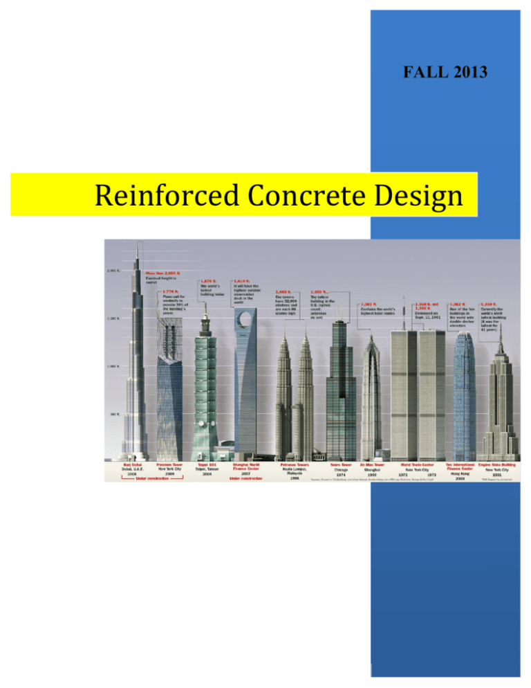
FALL 2013 C C Reinforced Concrete Design CIVL 4135 • ii 1 Chapter 1. Introduction 1.1. Reading Assignment Chapter 1 Sections 1.1 through 1.8 of text. 1.2. Introduction In the design and analysis of reinforced concrete members, you are presented with a problem unfamiliar to most of you: “The mechanics of members consisting of two materials.” To compound this problem, one of the materials (concrete) behaves differently in tension than in compression, and may be considered to be either elastic or inelastic, if it is not neglected entirely. Although we will encounter some peculiar aspects of behavior of concrete members, we will usually be close to a solution for most problems if we can apply the following three basic ideas: • Geometry of deformation of sections will be consistent under given types of loading; i.e., moment will always cause strain to vary linearly with distance from neutral axis, etc. • Mechanics of materials will allow us to relate stresses to strains. • Sections will be in equilibrium: external moments will be resisted by internal moment, external axial load will be equal to the sum of internal axial forces. (Many new engineers overly impressed speed and apparent accuracy of modern structural analysis computational procedures think less about equilibrium and details). We will use some or all of these ideas in solving most of the analysis problems we will have in this course. Design of members and structures of reinforced concrete is a problem distinct from but closely related to analysis. Strictly speaking, it is almost impossible to exactly analyze a concrete structure, and to design exactly is no less difficult. Fortunately, we can make a few fundamental assumptions which make the design of reinforced concrete quite simple, if not easy. A problem unique to the design of reinforced concrete structures is the need to detail each member throughout. Steel structures, in general, require only the detailed design of connections. For concrete structures, we must determine not only the area of longitudinal and lateral reinforcement required in each member, but also the way to best arrange and connect the reinforcement to insure acceptable structural performance. This procedure can be made reasonably simple, if not easy. Purpose of this course is to establish a firm understanding of behavior of reinforced concrete structures, then to develop method used in current practice and to achieve familiarity with codes and specifications governing practical design. In this course we will learn to understand the basic performance of concrete and steel as structural materials, and the behavior of reinforced concrete members and structures. If we understand the basic concepts behind code provisions for design, we will be able to: • Approach the design in a more knowledgeable fashion, not like following a black box; and • Understand and adapt the changes in code provisions better and faster. The overall goal is to be able to design reinforced concrete structures that are: • Safe • Economical • Efficient Reinforced concrete is one of the principal building materials used in engineered structures because: • Low cost • Weathering and fire resistance • Good compressive strength • Formability all these criteria make concrete an attractive material for wide range of structural applications such as buildings, dams, reservoirs, tanks, etc. 1.3. Design Codes and Specifications Buildings must be designed and constructed according to the provisions of a building code, which is a legal document containing requirements related to such things as structural safety, fire safety, plumbing, ventilation, and accessibility to the physically disabled. A building code has CIVL 4135 Chapter 1. Introduction • 2 the force of law and is administered by a governmental entity such as a city, a county, or for some large metropolitan areas, a consolidated government. Building codes do not give design procedures, but specify the design requirements and constraints that must be satisfied. Of particular importance to the structural engineer is the prescription of minimum live loads for buildings. While the engineer is encouraged to investigate the actual loading conditions and attempt to determine realistic values, the structure must be able to support these specified minimum loads. Although some large cities write their own building codes, many municipalities will adopt a “model” building code and modify it to suit their particular needs. Model codes are written by various nonprofit organizations in a form that is easily adopted by a governmental unit. Among the more popular are the BOCA National Building Code, the Uniform Building Code, the Standard Building Code, and International Building Code (IBC 2012). A related document, similar in form to a building code, is ASCE 7-10, Minimum Design Loads for Buildings and other Structures. This standard is intended to provide load requirements in a format suitable for adoption by a building code. United States does not have a national code governing structural concrete; • ACI Code (American Concrete Institute); • ACI commentary provides background material rational for code provisions; • Highway Bridges are designed according to “AASHTO” which stands for American Association of State Highway and Transportation Officials; • AREA stands for American Railway Engineers Association; This is manual of railway engineering. 1.4. Loads Loads that act on structures can be divided into three general categories: 1.4.1. Dead Loads Dead loads are those that are constant in magnitude and fixed in location throughout the lifetime of the structure such as: floor fill, finish floor, and plastered ceiling for buildings and wearing surface, sidewalks, and curbing for bridges. 1.4.2. Live Loads Live loads are those that are either fully or partially in place or not present at all, may also change in location; the minimum live loads for which the floors and roof of a building should be designed are usually specified in building code that governs at the site of construction (see Table 1 - “Minimum Design Loads for Buildings and Other Structure.”) CIVL 4135 Chapter 1. Introduction • 3 1.4.3. Environmental Loads Environmental Loads consist of wind, earthquake, and snow loads. such as wind, earthquake, and snow loads. 1.5. Serviceability Serviceability requires that • Deflections be adequately small; • Cracks if any be kept to a tolerable limits; • Vibrations be minimized. CIVL 4135 Chapter 1. Introduction • 4 CIVL 4135 Chapter 1. Introduction • 5 CIVL 4135 Chapter 1. Introduction • 6 CIVL 4135 Chapter 1. Introduction • 7 1.6. Safety A structure must be safe against collapse; strength of the structure must be adequate for all loads that might act on it. If we could build buildings as designed, and if the loads and their internal effects can be predicted accurately, we do not have to worry about safety. But there are uncertainties in: • Actual loads; • Forces/loads might be distributed in a manner different from what we assumed; • The assumptions in analysis might not be exactly correct; • Actual behavior might be different from that assumed; • etc. Finally, we would like to have the structure safe against brittle failure (gradual failure with ample warning permitting remedial measures is preferable to a sudden or brittle failure). 1.7. Design Basis Two philosophies of design have long been prevalent. The working stress method, focusing on conditions at service load (that is, when the structure is being used), was the principal method used from the early 1900s until the early 1960s. Today, with few exceptions, the strength design method is used, focusing on conditions at loads greater than service loads when failure may be immanent. The strength design method is deemed conceptually more realistic to establish structural safety. 1.8. Strength Design (or Ultimate Strength Design) • Since 1971 the ACI Code has been totally a strength code with “strength” meaning ultimate. • Select concrete dimensions and reinforcements so that the member strength are adequate to resist forces resulting from certain hypothetical overload stages, significantly above loads expected actually to occur in service. The design concept is known as “strength design.” Based on strength design the nominal strength of a member must be calculated on the basis of inelastic behavior of material. In other words, both reinforcing steel and concrete behave inelastically at ultimate strength condition. CIVL 4135 Chapter 1. Introduction • 8 The strength design method may be expressed by the following, Strength provide ≥ Strength required to carry factored loads (1.1) where the “strength provided” such as moment strength is computed in accordance with rules and assumptions of behavior prescribed by a building code, and the “strength required” is that obtained by performing a structural analysis using the factored loads. The design procedure is roughly as follows: • Multiply the working loads by the load factor to obtain the failure loads. • Determine the cross-sectional properties needed to resist failure under these loads. (A member with these properties is said to have sufficient strength, and would be at the verge of failure when subjected to the factored loads.) • Proportion your members that have these properties. 1.9. Allowable Stress Design • As an alternate to the strength design method, members may be proportioned so that stresses in the steel and concrete resulting from normal service loads are within specified limits (an allowable, or permissible, stress or load). These limits, known as allowable stresses are only fractions of the failure stresses of the material. Allowable stress design is also referred to as “working stress design.” • For example in design of steel structures, this allowable stress will be in the elastic range of the material and will be less than the yield stress Fy. A typical value might be 0.60Fy. The allowable stress is obtained by dividing either the yield stress Fy or the tensile strength Fu by a factor of safety. This approach to design is also called elastic design or working stress design. Working stresses are those due to the working loads, which are the applied loads. A properly designed member will be stressed to no more than the allowable stress when subjected to working loads. The working stress method may be expressed by the following: f ≤ allowable stresses ( f allowable ) (1.2) where: f CIVL 4135 = An elastically computed stress, such as by using the flexure formula f = Mc/I for beam. Chapter 1. Introduction • 9 fallow = A limiting stress prescribed by a building code as a percentage of the compressive strength f c′ for concrete, or of the yield stress f y for the steel reinforcing bars. 1.10. Safety Provisions of the ACI Code Load factors are applied to the loads, and a member is selected that will have enough strength to resist the factored loads. In addition, the theoretical strength of the member is reduced by the application of a resistance factor. The criterion that must be satisfied in the selection of a member is Factored Strength ≥ Factored Load (1.3) In this expression, the factored load is actually the sum of all working loads to be resisted by the member, each multiplied by its own load factor. For example, dead loads will have load factors that are different from those for live loads. The factored strength is the theoretical strength multiplied by a strength reduction factor. Equation (1.3) can therefore be written as Nominal Strength X Strength Reduction Factor ≥ Load X Load Factors (1.4) Since the factored load is a failure load greater than the actual working loads, the load factors are usually greater than unity. On the other hand, the factored strength is a reduced, usable strength and the resistance factor is usually less than unity. The factored loads are the loads that bring the structure or member to its limit. 1.11. Required Strength (Section 9.2 of the ACI Code) The required strength U is expressed in terms of factored loads, or related internal moments and forces. Factored loads are the loads specified in the general building code multiplied by appropriate factors. The factor assigned is influenced by the degree of accuracy to which the load effect can be determined and the variation which might be expected in the load during the lifetime of the structure. Dead loads are assigned a lower load factored than live load because they can be determined more accurately. Load factors also account for variability in the structural analysis used to compute moments and shears. The code gives load factors for specific combinations of loads. In assigning factors to combinations of loading, some consideration is given to the probability of simultaneous occurrence. While most of the usual combinations of loadings are included, the designer should not assume that all cases are covered. CIVL 4135 Chapter 1. Introduction • 10 Various load combinations must be considered to determine the most critical design condition. This is particularly true when strength is dependent on more than one load effect, such as strength for combined flexure and axial load or shear strength in members with axial load. Since the ACI 318 Building Code is a national code, it has to conform to the International Building Code, IBC2012 and in turn be consistent with the ASCE-7 Standard on Minimum Design Loads for Buildings and Other structures. These two standards contain the same probabilistic values for the expected safety resistance factors ΦiRn where Φ is a strength reduction factor, depending on the type of stress being considered in the design such as flexure, shear, or compression, etc. Table 1.2. Factored Load Combinations for Determining Required Strength U in ACI Code (ACI Section 9.2) Condition Factored Loads ACI Equation (9-1) U = 1.4(D + F) ACI Equation (9-2) U = 1.2(D + F + T) + 1.6(L + H) + 0.5(Lr or S or R) ACI Equation (9-3) U = 1.2D + 1.6(Lr or S or R) + (1.0L or 0.8W) ACI Equation (9-4) U = 1.2D + 1.6W + 1.0L + 0.5(Lr or S or R) ACI Equation (9-5) U = 1.2D + 1.0E + 1.0L + 0.2S ACI Equation (9-6) U = 0.9D + 1.6W + 1.6H ACI Equation (9-7) U= = 0.9D + 1.0E + 1.6H Due Regard is to be given to sign in determining U for combinations of loadings, as one type of loading may produce effects of opposite sense to that produced by another type. The load combinations with 0.9D are specifically included for the case where a higher dead load reduces the effects of other loads. The loading case may also be critical for tension controlled column sections. In such a case a reduction in axial load and an increase in moment may result in critical load combination. Except for • The load factor on L in Equation (9-3) to (9-5) shall be permitted to be reduced to 0.5 except for garages, areas occupied as places of public assembly, and all areas where the live load L is greater than 100 lb/ft2. • Where wind load W has not been reduced by a directionality factor, it shall be permitted to use 1.3W in place of 1.6W in Equations (9-4) and (9-6). CIVL 4135 Chapter 1. Introduction • 11 • Where earthquake load E is based on service-level seismic forces, 1.4E shall be used in place of 1.0E in Equations (9-5) and (9-7). • The load factor on H shall be equal to zero in Equation (9-6) and (9-7) if the structural action due to H counteracts that due to W or E. Where lateral earth pressure provides resistance to structural actions from other forces. It shall not be included in H but shall be included in the design resistance. Read ACI Sections 9.2.2 through 9.2.5. 1.12. Reduction in Live Load It is reasonable to assume that the “full” intensity of live load does not cover the entire floor area. Therefore, members having an influence area of 400 ft2 or more can be designed for a reduced live load from the following equation: ⎡ 15 ⎤ L = L0 ⎢0.25 + ⎥ AI ⎥⎦ ⎢⎣ (1.5) where: L = Reduced design live load per square foot of area supported by the member, L0 = Unreduced design live load per square foot of area, AI = Influence area: For other than cantilevered construction, AI is 4 times the tributary area for a column; 2 times tributary area for beams, or equal area for a two-way slab. The reduce design live load cannot be less than 50% of the unit live load L0 for member supporting one floor or less than 40% of the unit live load L0 for members supporting two or more floors. For live load of 100 lb/ft2 or less no reduction can be made for areas used as places of public assembly, except that in the case of garages for passenger cars a reduction of up to 20% can be made. Live loads in all other cases not stipulated by the code cannot be reduced except as accepted by the jurisdictional authority. CIVL 4135 Chapter 1. Introduction • 12 1.13. Design Strength (Section 9.3 of the ACI Code) The strength of a particular structural unit calculated using the current established procedures is termed “nominal strength.” For example, in the case of a beam the resisting moment capacity of the section calculated using the equations of equilibrium and properties of concrete and steel is called the “nominal moment capacity” Mn of the section. The purpose of the strength reduction factor f are (MacGregor, 1976; and Winter, 1979): • to allow for under-strength members due to variations in material strengths and dimensions • to permit for inaccuracies in the design provisions • to reflect the degree of ductility and required probability of the member under the load effects being considered • to reflect the importance of the member in the structure. CIVL 4135 Chapter 1. Introduction • 13 Table 1.3. Strength Reduction Factors, F, of the ACI Code. (ACI Section 9.3) Kind of Strength 9.3.2.1. Tension controlled sections as defined in 10.3.4 9.3.2.2. Compression controlled sections as defined in 10.9.3 (a) Members with spiral reinforcement (b) Other members For sections in which the net tensile strain in the extreme tension steel is between the limits for compression controlled and tension controlled sections, Φ may be increased in from that for compression controlled section to 0.90 as the net tensile strain in the extreme tension steel at nominal strength increases from the compression-controlled strain limit 0.005. Strength Reduction Factor Φ 0.9 0.75 0.65 Alternatively, when Appendix B is used, for members in which fy does not exceed 60,000 psi, with symmetrical reinforcement, and with (h-d'-ds)/h not less than 0.7, Φ may be increased linearly to 0.90 as ΦPn decreases from 0.1 f c′Ag to zero. For other reinforced members, Φ may be increased linearly to 0.90 as Φ Pn decreases from 0.1 f c′Ag to Φ Pn, whichever is smaller, to zero 9.3.2.3. Shear and torsion 0.75 9.3.2.4. Bearing on Concrete 9.3.2.7. Flexure sections without axial load in pretensioned members where strand embedment is less than development length as provided in 12.9.1.1 0.65 9.3.5. Plain Concrete 0.55 CIVL 4135 0.75 Chapter 1. Introduction • 14 1.14. Example Compute Factored load to be used in the design of a column subjected to the following load effects: 9 kips compression from dead load, 5 kips compression from roof live load, 6 kips compression from snow, 7 kips compression from accumulated rain, and 8 kips compression from wind. Assume live load is greater than 100 lb/ft2. Solution: Condition Factored Loads ACI Equation (9-1) U = 1.4(D + F) U = 1.4(9) = 12.6 kips ACI Equation (9-2) U = 1.2(D + F + T) + 1.6(L + H) + 0.5(Lr or S or R) U = 1.2D + 1.6L + 0.5R U = 1.2(9) + 1.6(0) + 0.5(7) U = 14.3 kips ACI Equation (9-3) U = 1.2D + 1.6(Lr or S or R) + (1.0L or 0.8W) U = 1.2(D) + 1.6(R) + 0.8W U = 1.2(9) + 1.6(7) + 0.8(8) U = 28.4 kips ACI Equation (9-4) U = 1.2D + 1.6W + 1.0L + 0.5(Lr or S or R) U = 1.2D + 1.6W + 0.5L + 0.5R U = 1.2(9) + 1.6(8) + 0.5(0) + 0.5(7) U = 27.1 kips ACI Equation (9-5) U = 1.2D + 1.0E + 1.0L + 0.2S U = 1.2(9) + 0.2(6) U = 12 kips ACI Equation (9-6) U = 0.9D + 1.6W + 1.6H U = 0.9(9) + 1.6(8) U = 20.9 kips ACI Equation (9-7) U= = 0.9D + 1.0E + 1.6H U = 0.9(9) U = 8.1 kips Therefore, U = 28.4 kips controls. CIVL 4135 Chapter 1. Introduction • 15 1.15. Ultimate Strength vs. Working Stress Design For D and L only 1.2D + 1.6L ≤ φ Rn or 1.4D ≤ φ Rn ............................................ (1.6) Working stress design 1.67 D + 1.67 L ≤ Rn ................................................................................. (1.7) Assume a strength reduction factor of φ = 0.9, Equation (1.7) becomes: 1.5D + 1.5L ≤ 0.9Rn ................................................................................. (1.8) Therefore, the ratio for Ultimate Strength Equation (1.6) to Working Stress Equation (1.8) becomes CIVL 4135 Ratio = 1.2 D + 1.6 L or 1.5D + 1.5L Ratio = 1.2 + 1.6( L / D) or 1.5 + 1.5( L / D) 1.4 D 1.4 ............................................ (1.9) .......................................... (1.10) Chapter 1. Introduction • 16 1.16. References MacGregor, J.G. (1976). “Safety and Limit States Design for Reinforced Concrete.” Canadian Journal of Civil Engineering, 3(4), December, pp. 484-513. Winter, G. (1979). “Safety and Serviceability Provisions in the ACI Building Code.” Concrete Design: U.S. and European Practices, SP-59, American Concrete Institute, Detroit, 1979, pp. 3549 Nawy, E.G.. (2003). Reinforced Concrete A Fundamental Approach. Fifth Edition, Prentice Hall. CIVL 4135 Chapter 1. Introduction • 17 Homework Set 1 Draw the shear and moment diagrams for the beams shown below. 10 kips 10 kips 20 kips 10 kips 10 kips (A) 8’-0” 6’-0” 8’-0” 7’-0” 10’-4.5” 20 kips w = 1.5 k/ft (B) 20’-9” w = 2.5 k/ft (C) 20’-9” 50 kips 50 kips w = 1.0 k/ft (D) 20’-9” CIVL 4135 10’-6” Chapter 1. Introduction • 18 Homework Set 1 - Continued E. The reinforced concrete bridge pier shown below supports a three-girder structural steel highway bridge. Two loading cases are shown below. For each loading condition, draw the shear and moment diagrams for the beam. Determine the moment for which the beam must be designed. Determine the moment for which the column must be designed. PD + PL PD + PL PD + PL 5’-9” 5’-9” Load case 1 PD = 36 kips PL = 40 kips 5’-0” 18” 5’-0” PD + PL PD 5’-9” PD + PL 5’-9” Load case 2 5’-0” CIVL 4135 18” 5’-0” Chapter 1. Introduction • 19 Homework Set 1 - Continued F. A weightless cantilever supports a concentrated service load of magnitude P as shown below. The beam is a reinforced concrete having both flexure and transverse steel. Denote the theoretical shear and moment strength of the beam as Vn and Mn. Reliable strengths are obtained by the appropriate factors, φ, respectively. Fictitious values for these factors are given below. Factors Shear Flexure φ 0.85 0.90 If the live load factor is 1.7, and the theoretical flexure and shear capacity are 110 kip-ft and 11 kip, what magnitude of P would be permitted using strength design? 11’ 9” Answer: P CIVL 4135 = ? Chapter 1. Introduction • 20

![Structural Applications [Opens in New Window]](http://s3.studylib.net/store/data/006687524_1-fbd3223409586820152883579cf5f0de-300x300.png)
