ReadMe file
advertisement
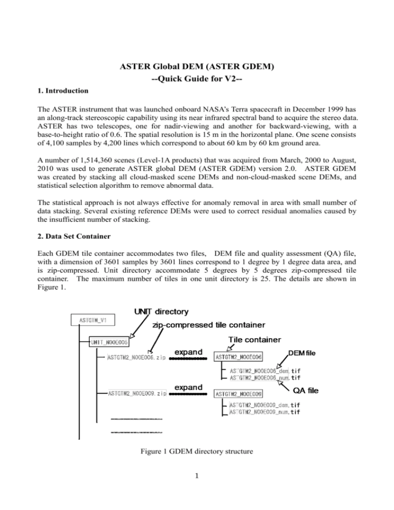
ASTER Global DEM (ASTER GDEM) --Quick Guide for V2-1. Introduction The ASTER instrument that was launched onboard NASA’s Terra spacecraft in December 1999 has an along-track stereoscopic capability using its near infrared spectral band to acquire the stereo data. ASTER has two telescopes, one for nadir-viewing and another for backward-viewing, with a base-to-height ratio of 0.6. The spatial resolution is 15 m in the horizontal plane. One scene consists of 4,100 samples by 4,200 lines which correspond to about 60 km by 60 km ground area. A number of 1,514,360 scenes (Level-1A products) that was acquired from March, 2000 to August, 2010 was used to generate ASTER global DEM (ASTER GDEM) version 2.0. ASTER GDEM was created by stacking all cloud-masked scene DEMs and non-cloud-masked scene DEMs, and statistical selection algorithm to remove abnormal data. The statistical approach is not always effective for anomaly removal in area with small number of data stacking. Several existing reference DEMs were used to correct residual anomalies caused by the insufficient number of stacking. 2. Data Set Container Each GDEM tile container accommodates two files, DEM file and quality assessment (QA) file, with a dimension of 3601 samples by 3601 lines correspond to 1 degree by 1 degree data area, and is zip-compressed. Unit directory accommodate 5 degrees by 5 degrees zip-compressed tile container. The maximum number of tiles in one unit directory is 25. The details are shown in Figure 1. Figure 1 GDEM directory structure 1 The names of individual data tiles refer to the latitude and longitude at the geometric center of lower-left (southwest) corner pixel. For example, the coordinates of the lower-left corner of the tile ASTGTM2_N00E006 tile are 0 degree north latitude and 6 degrees east longitude. ASTGTM2_N00E006_dem and ASTGTM2_N00E006_num files accommodate DEM and QA data, respectively. The unit name also refer to the latitude and longitude at lower left corner of 5 degree by 5 degree area. The rows at the north and south edges as well as the column at the east and west edges of each cell overlap and are identical to the edge row and column in the adjacent cell. The data coverage is north 83 degrees to south 83 degrees. Tiles including at lease 0.01 % land area were processed. The number of tiles is 22,702 for version 2 data set. 3. Data Formats Data formats are summarized in Table 1. Table 1 Data formats Tile Size 3601 x 3601 (1 degree by 1 degree) Posting interval 1 are-second Geographic coordinates Geographic latitude and longitude DEM output format GeoTiff, signed 16 bits, and 1m/DN Referenced to the WGS84/EGM96 geoid Special DN values -9999 for void pixels, and 0 for sea water body Coverage North 83 degrees to south 83 degrees, 22,600 tiles for V1 4. Anomaly Correction The cloud masking and the statistical approach were used to select the effective data for stacking. The cloud masking can not completely remove the clouds, In addition, the statistical approach is not always effective for anomaly removal in case of small number of observed data. At least, three stacking data will be necessary for it. Existing DEMs were used to correct anomaly as reference data. Table 2 shows the list of the reference DEM used for version 1 data. The anomaly data are replaced by the reference data after adjusting offsets between ASTER GDEM and the reference DEM data. 2 Table 2 Reference DEM list used for version 1 SRTM3 V3 (Void filled version) Posting: 3 seconds Coverage: north 60 degrees – south 56 degrees Only about 90 % tiles of SRTM V2 are void filled SRTM3 V2 Posting: 3 seconds Coverage: north 60 degrees – south 56 degrees Posting: 1 second NED (US National Elevation Data) CDED (Canada DEM) Alaska DEM Posting: 3 seconds for latitude 3, 6 and 12 seconds for longitude depending on latitude Coverage: all Canada territory Posting: 2 x 2 seconds Coverage: all Alaska territory 5. QA Plane The QA plane file that is included in the tile container is used to describe number of stack by positive values and replaced reference data by negative values as shown in Table 3. The tile size, posting interval, and geometric formats are consistent with DEM data shown in Table 1. Table 3 Reference data vs negative number of QA plane SRTM3 V3 -1 SRTM3 V2 -2 NED -5 CDED -6 Alaska DEM -11 6. Quality Limitation In some area, the number of data stack is not sufficient to completely remove anomaly. In addition, the reference data is not necessarily available for anomaly correction in entire area. Those situation will give rise to difficulty for completely remove all anomalies. Therefore, users must be aware that data may be anomalous in pixels with the small number of stacking data equal to 2 or less. 3 7. Key Processing Factors The change in the key processing factors from Version 1 to Version 2 is listed in Table 4. Table 4 Key processing factors Key processing factor Version 1 Version 2 Number of input scene DEMs 1,264,118 1,514,350 Posting interval 1 arc-second 1 arc-second Correlation kernel size 9 by 9 pixels 5 by 5 pixels 12 sq. km 1.0 sq. km Not applied Applied 40 m 40 m -5 m offset observed V1 offset revomed June 29th, 2009 Scheduled to be middle of October, 2011 Minimum water body detection size Water body post processing Filtering threshold value Offset Release data 4

