Objectives
Frame Relay
Describe the fundamental concepts of Frame Relay
technology including Frame Relay operation, Frame
Relay implementation requirements, Frame Relay maps,
and LMI operation.
Configure a basic Frame Relay PVC including
configuring and troubleshooting Frame Relay on a router
serial interface and configuring a static Frame Relay
map.
Describe advanced concepts of Frame Relay technology
including Frame Relay sub-interfaces, Frame Relay
bandwidth and flow control.
Configure an advanced Frame Relay PVC including
solving reachability issues, configuring Frame Relay
sub-interfaces, verifying and troubleshooting Frame
Relay configuration.
Accessing the WAN – Chapter 3
2
ITE I Chapter 6
© 2006 Cisco Systems, Inc. All rights reserved.
Cisco Public
1
Frame Relay WAN Technology
PVCs
Frame Relay has become the most widely used WAN
technology in the world.
The connection through a Frame Relay network
between two DTEs is called a permanent virtual circuit
(PVC).
It is a packet switched network
PVCs are preconfigured by the carrier,
Connects LANs over a geographical area
PVCs provide a bidirectional communication path from
one DTE to another.
A router on each LAN is the DTE.
A serial connection, such as a T1/E1 leased line,
connects the router to the Frame Relay switch (the DCE
device) of the carrier at the nearest point-of-presence
(POP) for the carrier.
Each PVC is identified by a 10-bit DLCI (Data-link
connection identifier)
Can also connect an individual terminal to the Frame
Relay network using a Frame Relay access device
(FRAD) as the DTE.
Usually, DLCIs 0 to 15 and 1008 to 1023 are reserved
for special purposes.
A DLCI only has local significance.
3
4
Frame Relay Encapsulation
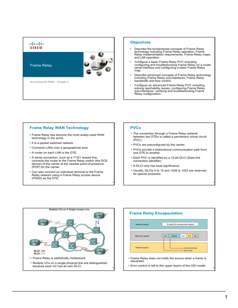
Frame Relay is statistically multiplexed.
Multiple VCs on a single physical line are distinguished
because each VC has its own DLCI.
Frame Relay does not notify the source when a frame is
discarded.
5
Error control is left to the upper layers of the OSI model.
6
1
Frame Relay Encapsulation
Frame Relay Topologies
Every network can be viewed as being one of three
topology types:
encapsulation frame-relay [cisco | ietf]
Star (Hub and Spoke)
Each spoke has a single connection to the hub
cisco – Proprietary standard, the default
ietf - Non-proprietary. Use with non-Cisco routers
Requires the minimum number of connections
Full mesh
Example:
Each DTE has a connection to every other DTE
int s0/0
ip address 10.1.1.1 255.255.255.0
encapsulation frame-relay
no shutdown
Partial mesh.
With partial mesh, there are more interconnections
than required for a star arrangement, but not as
many as for a full mesh.
7
8
Network Address-to-DLCI Mapping
Address-to-DLCI mapping can be accomplished either
by static or dynamic mapping.
A static mapping is configured manually on the router
Dynamic mapping uses the Inverse Address Resolution
Protocol (ARP) to obtain Layer 3 addresses of other
stations from the Layer 2 DLCI addresses.
An address-to-DLCI mapping table is populated by
sending a request on each PVC for the next hop
address
Each DTE has one physical connection to the Frame
Relay cloud
On Cisco routers, Inverse ARP is enabled by default
The carrier configures PVCs between the DTEs,
depending on the topology required by the customer
To view the address-to-dlci mappings:
show frame-relay map
9
Local Management Interface (LMI)
10
Local Management Interface (LMI)
LMI is an extension to Frame Relay that operates between
the router (DTE) and the local Frame Relay switch (DCE)
The LMI type configured on the router must match the type
used by the service provider:
Cisco - original LMI extension
Ansi
- the ANSI standard T1.617 Annex D
q933a - the ITU standard Q933 Annex A
It allows the router to dynamically acquire information
about the status of the Frame Relay network
LMI provides the following extensions:
- A keepalive mechanism (every 10 secs by default)
- Status information about each PVC configured
- Multicasting
- Global addressing
- Simple flow control
frame-relay lmi-type [cisco | ansi | q933a]
From IOS 11.2, the default LMI autosense feature detects
the LMI type
LMI status messages combined with Inverse ARP
messages allow a router to associate network layer and
data link layer addresses.
11
12
2
Full-Mesh Frame Relay Configuration
All router interfaces are in the same subnet
13
Frame Relay Dynamic Mapping Example
14
Frame Relay Static Map Example
int s0/0/0
ip address 10.1.1.1 255.255.255.0
encapsulation frame-relay
no shutdown
frame-relay lmi-type ansi
int s0/0/0
ip address 10.1.1.1 255.255.255.0
encapsulation frame-relay
no shutdown
no frame-relay inverse-arp
frame-relay map ip 10.1.1.2 102 broadcast
frame-relay map ip 10.1.1.3 103 broadcast
frame-relay lmi-type ansi
LMI status messages combined with Inverse ARP
messages allow a router to associate network layer and
data link layer addresses.
frame-relay map protocol protocol-address dlci
[broadcast][cisco|ietf]
Default encapsulation is Cisco, so the other routers must
also be configured with the same encapsulation, not IETF
Because FR does not support broadcast traffic, using the
broadcast keyword is a simplified way to forward routing
updates. Required by RIP, EIGRP and OSPF.
Assume the FR-Switch LMI type is Ansi
15
Problems on NBMA networks
16
Reachability Issues
Frame Relay network provides NBMA connectivity (i.e.
non-broadcast multi-access).
To support broadcast routing updates, each update must
be replicated on each PVC
Replicated broadcast packets can consume bandwidth
and cause significant latency to user traffic.
Split horizon can produce reachability problems on
routers that support multiple connections over a single
physical interface.
Solution: Disable split horizon?
This problem only occurs when partial mesh topology is
used.
With full-mesh topology – no problem with split-horizon
rule.
Only IP allows you to disable split horizon. Could result in
routing loops.
17
The preferred solution is to use subinterfaces.
18
3
Problems on NBMA networks
Configuring subinterfaces
To enable the forwarding of broadcast routing updates
in a Frame Relay network, you can configure the router
with logically assigned subinterfaces.
Frame Relay subinterfaces can be configured in either
point-to-point or multipoint mode:
Point-to-point
Each pair of the point-to-point routers is on its own
subnet, and each point-to-point subinterface has a
single DLCI.
Here, topology is hub-and-spoke, with R1 the hub
Multipoint
All the participating interfaces are in the same
subnet. Routing update traffic is subject to the split
horizon rule.
Each PVC connects two interfaces point-to-point, so
requires separate IP subnet
19
Configuring FR subinterfaces
R1’s s0/0/0 interface must be configured with two
subinterfaces
20
Configuring FR subinterfaces
R1(config-if)# interface s0/0.103 [multipoint | point-to-point]
hostname R1
!
int s0/0/0
no ip address
encapsulation frame-relay
no shutdown
!
int s0/0/0.102 point-to-point
ip address 10.1.1.1 255.255.255.252
frame-relay interface-dlci 102
!
int s0/0/0.103 point-to-point
ip address 10.1.1.5 255.255.255.252
frame-relay interface-dlci 103
multipoint – all routers exist in the same subnet.
point-to-point – each pair of routers has its own subnet
R1(config-subif)# frame-relay interface-dlci dlci
This associates a DLCI with the subinterface (the LMI
does not know about subinterfaces)
This command is only ever used with subinterfaces.
21
Paying for Frame Relay - Terminology
Access rate or port speed
- capacity of the local loop. It is not possible to send data
at higher than port speed.
Committed Information Rate (CIR)
- negotiated with service providers for each PVC.
The Committed Burst Information Rate (CBIR)
- negotiated for each PVC
Excess Burst Size (BE)
– remaining bandwidth determined by port speed.
Any network capacity that is being unused is made available
or shared with all customers, usually at no extra charge.
This allows customers to "burst" over their CIR. A "burst" is
23
assumed to last no more than a few seconds
22
Paying for Frame Relay - Cost components
Access or port speed:
The cost of the access line from the DTE to the DCE.
This line is charged based on the port speed that has
been negotiated and installed.
The number of PVCs
Each PVC has a CIR
Customers normally choose a CIR lower than the port
speed or access rate. This allows them to take
advantage of bursts.
Note that the distance between DTEs and the total
amount of data put on the network does not affect the cost
24
4
Frame Relay Bursting
Flow Control
Frame Relay implements simple congestion-notification
mechanisms:
- Forward Explicit Congestion Notification (FECN)
- Backward Explicit Congestion Notification (BECN).
Frames above the CIR have the DE bit set to 1,
marking it as eligible to be discarded, should the
network be congested
25
FECN and BECN are each controlled by a single bit
contained in the frame header.
26
Flow Control
Frames
BECN
FECN
Downstream devices are warned of the queue by
setting the FECN bit.
Upstream devices are warned by setting the BECN bit
– even though they may not have contributed to the
congestion
27
28
29
30
5
Summary
Summary
Frame relay is the most widely used WAN technology
because it:
Configuring frame relay requires
–Enable frame relay encapsulation
–Configuring either static or dynamic mapping
–Considering split horizon problems that develop when
multiple VCs are placed on a single physical interface
–Provides greater bandwidth than leased line
–Reduces cost because it uses less equipment
–Easy to implement
Frame relay is associated with layer 2 of the OSI model
and encapsulates data packets in a frame relay frame
Factor affecting frame relay configuration
–How service provider has their charging scheme set up
Frame relay is configured on virtual circuits
Frame relay flow control
–DE
–FECN
–BECN
–These virtual circuits may be identified by a DLCI
Frame relay uses inverse ARP to map DLCI to IP
addresses
31
Summary
32
Lab 3.5.1: Basic Frame Relay Configuration
The following commands can be used to help verify
frame relay configuration
–Show interfaces
–Show frame-relay lmi
–Show frame-relay pvc ###
–Show frame-relay map
Use the following command to help troubleshoot a
frame relay configuration
–Debug frame-relay lmi
192.168.10.0 /24
33
hostname R1
!
int fa0/0
ip address 192.168.10.1 255.255.255.0
no shutdown
!
int s0/1
ip address 10.1.1.1 255.255.255.252
encapsulation frame-relay
no frame-relay inverse-arp
frame-relay map ip 10.1.1.2 102 broadcast
no shutdown
!
router eigrp 1
no auto-summary
network 10.0.0.0
network 192.168.10.0
!
end
Disable LMI and use a Static map
34
Task 5 - Create FR sub-interfaces
35
hostname R1
!
int fa0/0
ip address 192.168.10.1 255.255.255.0
no shutdown
!
int s0/1
no ip address
encapsulation frame-relay
no frame-relay inverse-arp
frame-relay map ip 10.1.1.2 102 broadcast
no shutdown
!
int s0/1.112 point-to-point
ip address 10.1.1.5 255.255.255.252
frame-relay interface-dlci 112
!
end
36
6


