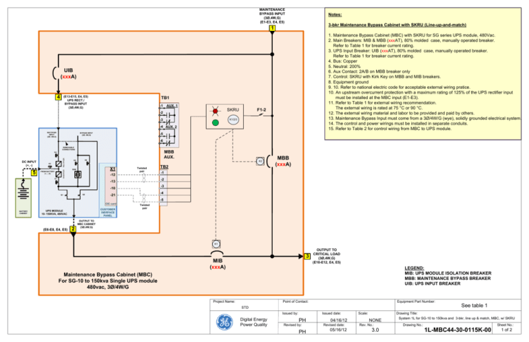
Visio-3-bkr MBC for SG10-150, 1L-MBC44-30-015k
advertisement

MAINTENANCE BYPASS INPUT (3Ø,4W,G) (E1-E3, E4, E5) Notes: 3-bkr Maintenance Bypass Cabinet with SKRU (Line-up-and-match) 1 1. Maintenance Bypass Cabinet (MBC) with SKRU for SG series UPS module, 480Vac. 2. Main Breakers: MIB & MBB (xxxAT), 80% molded case, manually operated breaker. Refer to Table 1 for breaker current rating. 3. UPS Input Breaker: UIB (xxxAT), 80% molded case, manually operated breaker. Refer to Table 1 for breaker current rating. 4. Bus: Copper 5. Neutral: 200% 6. Aux Contact: 2A/B on MBB breaker only 7. Control: SKRU with Kirk Key on MBB and MIB breakers. 8. Equipment ground 9. 10. Refer to national electric code for acceptable external wiring pratice. 10. An upstream overcurrent protection with a maximum rating of 125% of the UPS rectifier input must be installed at the MBC input (E1-E3). 11. Refer to Table 1 for external wiring recommendation. The external wiring is rated at 75 °C or 90 °C. 12. The external wiring material and labor to be provided and paid by others. 13. Maintenance Bypass Input must come from a 3Ø/4W/G (wye), solidly grounded electrical system. 14. The control and power wirings must be installed in separate conduits. 15. Refer to Table 2 for control wiring from MBC to UPS module. UIB (xxxA) 4 (E13-E15, E4, E5) UPS RECT./ BYPASS INPUT (3Ø,4W,G) TB1 -1 AUX. 1 F1-2 SKRU -2 K1/2/3 -3 -4 AUX. 2 RECTIFIER INPUT (3Ø, 3W,G) BYPASS INPUT (3Ø, 4W,G) -5 -6 REMOVABLE CONNECTIONS MBB AUX. 5 ~ K3 - FROM BATTERY (+, -, G) ~ K7 INVERTER DC INPUT (+, -) RECTIFIER K4 K6 K8 K2 X1 SSM Twisted pair -12 -3 -10 Q2 -1 -2 -13 Q1 TB2 MBB (xxxA) -4 -21 -5 CIC card BATTERY CABINET CUSTOMER INERFACE PANEL UPS MODULE 10- 150KVA, 480VAC (E6-E8, E4, E5) 2 Twisted pair OUTPUT TO MBC CABINET (3Ø,4W,G) K1 3 MIB (xxxA) OUTPUT TO CRITICAL LOAD (3Ø,4W,G) (E10-E12, E4, E5) LEGEND: MIB: UPS MODULE ISOLATION BREAKER MBB: MAINTENANCE BYPASS BREAKER UIB: UPS INPUT BREAKER Maintenance Bypass Cabinet (MBC) For SG-10 to 150kva Single UPS module 480vac, 3Ø/4W/G Project Name: Point of Contact: Equipment Part Number: STD Issued by: Digital Energy Power Quality Issued date: PH Revised by: PH 04/16/12 Revised date: 05/16/12 Scale: NONE Rev. No.: 3.0 See table 1 Drawing Title: System 1L for SG-10 to 150kva and 3-bkr, line up & match, MBC, w/ SKRU Drawing No.: Sheet No.: 1L-MBC44-30-0115K-00 1 of 2 Table 1- Maintenance Bypass Cabinet (MBC) Breaker Schedule, Lug size/quantity, and conductor size/quantity FROM UTILITY 1 BREAKER MBB/MIB MODEL (Trip) (EATON-C) (Trip) MBC014-010200-K100 EHD3 15A 25A 14 MBC014-010200-K600 HFD3 15A 25A 65 MBC024-030500-K100 EHD3 30A 50A 14 MBC024-030500-K600 HFD3 30A 50A 65 MBC034-050700-K100 EHD3 50A 70A 14 MBC034-050700-K600 HFD3 50A 70A 65 MBC044-060800-K100 EHD3 60A 80A 14 MBC044-060800-K600 HFD3 60A 80A 65 MBC054-081200-K100 EHD3/FDB3 80A 125A 14 MBC054-081200-K600 HFD3 80A 125A 65 MBC084-121700-K300 FD3 125A 175A 35 MBC084-121700-K600 HFD3 125A 175A 65 MBC104-152000-K300 FD3 150A 200A 35 MBC104-152000-K600 HFD3 150A 200A 65 MBC124-202500-K300 JDB3 200A 250A 35 MBC124-202500-K600 HJDB3 200A 250A 65 MBC154-253000-K300 KDB3 250A 300A 35 MBC154-253000-K600 HKDB3 250A 300A 65 UPS (KVA) 10 20 30 40 50 80 100 120 150 MBC PART NUMBER UIB kAIC@ 480Vac (PER PHASE) MAXIMUM CONDUCTOR SIZE (QTY) LUG SIZE (QTY) 2 FROM UPS OUTPUT 3 (PER PHASE) MAXIMUM CONDUCTOR SIZE (QTY) LUG SIZE (QTY) TO CRITICAL LOAD LUG SIZE (QTY) 4 (PER PHASE) MAXIMUM CONDUCTOR SIZE (QTY) TO UPS INPUT NEUTRAL (TOTAL) (PER PHASE) LUG SIZE (QTY) MAXIMUM CONDUCTOR SIZE (QTY) LUG SIZE (QTY) MAXIMUM CONDUCTOR SIZE (QTY) 5 GROUND (TOTAL) (PER POLE) DC DISCONNECT SIZE (A) LUG SIZE (QTY) (4) 3 25A (1) 14-1/0 (1) 3 MAXIMUM CONDUCTOR SIZE (QTY) LUG SIZE (QTY) UPS DC INPUT MAXIMUM CONDUCTOR SIZE (QTY) (1) 14-1/0 (1) 3 (1) 14-1/0 (1) 3 (1) 14-1/0 (1) 3 (1) 14-1/0 (1) 3 (4) #6-350 (4) 3 (1) 14-1/0 (1) 3 (1) 14-1/0 (1) 3 (1) 14-1/0 (1) 3 (1) 14-1/0 (1) 3 (4) #6-350 (4) 3 (4) #6-350 (4) 3 50A (1) 14-1/0 (1) 3 (1) 14-1/0 (1) 1 (1) 14-1/0 (1) 1 (1) 14-1/0 (1) 1 (1) 14-1/0 (1) 1 (4) #6-350 (4) 3 (4) #6-350 (4) 3 70A (1) 14-1/0 (1) 1 (1) 14-1/0 (1) 1 (1) 14-1/0 (1) 1 (1) 14-1/0 (1) 1 (1) 14-1/0 (1) 1 (4) #6-350 (4) 3 (4) #6-350 (4) 3 80A (1) 14-1/0 (1) 1 (1) 4-4/0 (1) 4/0 (1) 14-1/0 (1) 4/0 (1) 14-1/0 (1) 4/0 (1) 4-4/0 (1) 4/0 (4) #6-350 (4) 3 (4) #6-350 (4) 3 110A (1) 4-4/0 (1) 4/0 (1) 4-4/0 (1) 4/0 (1) 4-4/0 (1) 4/0 (1) 4-4/0 (1) 4/0 (1) 4-4/0 (1) 4/0 (4) #6-350 (4) 4/0 (4) #6-350 (4) 4/0 200A (1) 4-4/0 (1) 4/0 (1) 4-4/0 (1) 4/0 (1) 4-4/0 (1) 4/0 (1) 4-4/0 (1) 4/0 (1) 4-4/0 (1) 4/0 (4) #6-350 (4) 4/0 (4) 350 225A (1) 1-500 (1) 500 (1) 4-350 (1) 350 (1) 4-350 (1) 4-350 (1) 350 (1) 4-350 (1) 350 (4) 6-500 (4) 350 (4) 6-350 (4) 350 250A (1) 1-500 (1) 500 (1) 250-500 (1) 500 (1) 250-500 (1) 250-500 (1) 500 (1) 250-500 (1) 500 (4) 6-500 (4) 500 (4) 6-350 (4) 350 300A (1) 1-500 (1) 500 (1) 350 (1) 500 (4) #6-350 (4) #6-350 Table 2- Control Wiring From MBC to UPS module Terminating point In MBC TB2-1 Terminating point In UPS X1-12 (CIC card) TB2-2 X1-13 (CIC card) TB2-4 X1-10 (CIC card) TB2-5 X1-21 (CIC card) Wire Size Maximum Voltage & Current 18AWG 24V 1.25A 18AWG 24V 1.25A Circuit Function Note SKRU control (Key can be removed if UPS is on bypass) Twisted pair UPS control (UPS transfer is prohibited during testing) Twisted pair Project Name: Point of Contact: Equipment Part Number: STD Issued by: Digital Energy Power Quality Issued date: PH Revised by: PH 04/16/12 Revised date: 05/16/12 Scale: NONE Rev. No.: 3.0 See table 1 Drawing Title: System 1L for SG-10 to 150kva and 3-bkr, line up & match, MBC, w/ SKRU Drawing No.: Sheet No.: 1L-MBC44-30-0115K-00 2 of 2


