“Quick Select” Pressure Booster Design Worksheet
advertisement
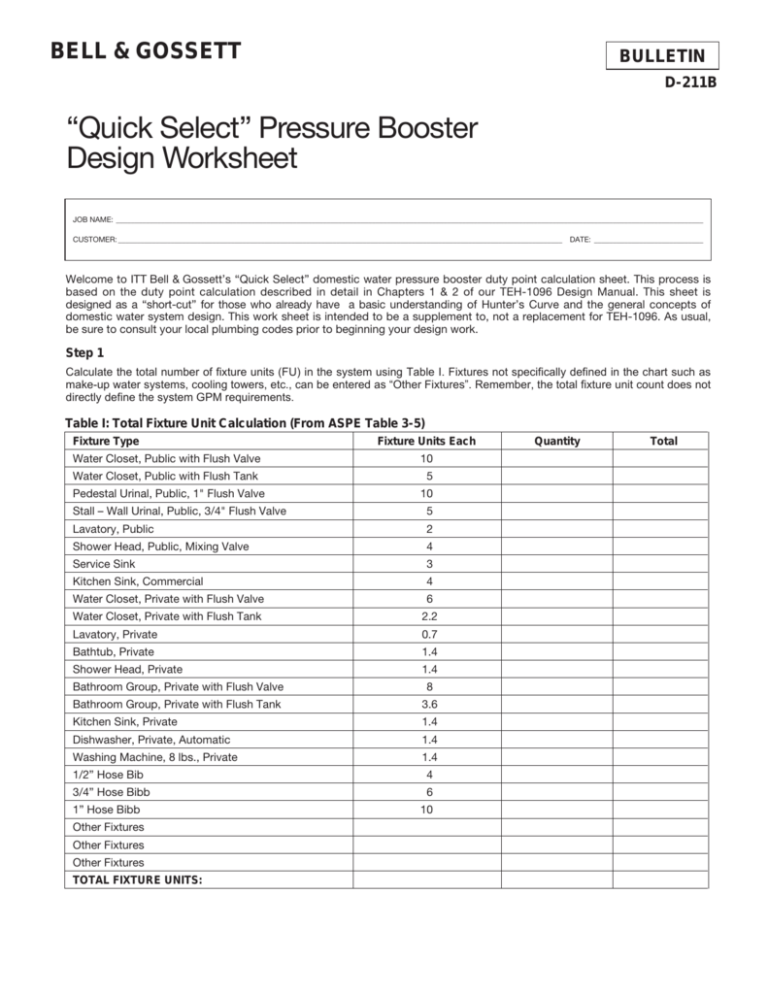
BELL & GOSSETT BULLETIN D-211B “Quick Select” Pressure Booster Design Worksheet JOB NAME: ____________________________________________________________________________________________________________________________________________________________ CUSTOMER: ______________________________________________________________________________________________________________________ DATE: _____________________________ Welcome to ITT Bell & Gossett’s “Quick Select” domestic water pressure booster duty point calculation sheet. This process is based on the duty point calculation described in detail in Chapters 1 & 2 of our TEH-1096 Design Manual. This sheet is designed as a “short-cut” for those who already have a basic understanding of Hunter’s Curve and the general concepts of domestic water system design. This work sheet is intended to be a supplement to, not a replacement for TEH-1096. As usual, be sure to consult your local plumbing codes prior to beginning your design work. Step 1 Calculate the total number of fixture units (FU) in the system using Table I. Fixtures not specifically defined in the chart such as make-up water systems, cooling towers, etc., can be entered as “Other Fixtures”. Remember, the total fixture unit count does not directly define the system GPM requirements. Table I: Total Fixture Unit Calculation (From ASPE Table 3-5) Fixture Type Fixture Units Each Water Closet, Public with Flush Valve 10 Water Closet, Public with Flush Tank 5 Pedestal Urinal, Public, 1" Flush Valve 10 Stall – Wall Urinal, Public, 3/4" Flush Valve 5 Lavatory, Public 2 Shower Head, Public, Mixing Valve 4 Service Sink 3 Kitchen Sink, Commercial 4 Water Closet, Private with Flush Valve 6 Water Closet, Private with Flush Tank 2.2 Lavatory, Private 0.7 Bathtub, Private 1.4 Shower Head, Private 1.4 Bathroom Group, Private with Flush Valve 8 Bathroom Group, Private with Flush Tank 3.6 Kitchen Sink, Private 1.4 Dishwasher, Private, Automatic 1.4 Washing Machine, 8 lbs., Private 1.4 1/2” Hose Bib 4 3/4” Hose Bibb 6 1” Hose Bibb Other Fixtures Other Fixtures Other Fixtures TOTAL FIXTURE UNITS: 10 Quantity Total Step 2 Step 2 Now the FU total must be converted to actual GPM requirements. Refer to Table II for conversion values. This conversion is based on Natural Bureau of Standards Report BMS79 by R.B. Hunter. This report is often referred to simply as Hunter’s Curve. Table II: FU to GPM Conversion Total FU Demand GPM 250 100 500 140 750 175 1000 200 1250 240 1500 275 1750 300 2000 325 2500 390 3000 440 4000 570 5000 665 6000 780 7000 875 8000 960 Step 3 The final step is to calculate the required pressure that the booster system must actually develop. Refer to Table III to perform this calculation. Table III: Pressure Boost Calculation 1. Static Pressure: Elevation of highest fixture above discharge of booster pump. ft / 2.31 = PSI 2. Piping Friction Loss Estimation Factor: Estimate friction loss at 10% of critical path piping length in feet. ft / 2.31 = PSI 3. Static Pressure + Friction Loss: PSI 4. Pressure Required at Highest Fixture: 30 PSI is a typical value but always consult local codes. PSI 5. Required System Pressure (3+4): PSI 6. Subtract Minimum Suction Pressure:* – 7. Required Boost: This is the pressure that the booster system will add on top of the suction pressure. PSI PSI *Be sure to account for backflow preventer pressure loss (typically ≈ 30 ft.) Pressure booster to be designed to deliver GPM @ PSIG boost. Pressure Booster Stocking Representative: Bell & Gossett © COPYRIGHT 1997, 2003 BY ITT INDUSTRIES, INC. PRINTED IN U.S.A. 4-03 USA Bell & Gossett 8200 N. Austin Avenue Morton Grove, IL 60053 Phone: (847) 966-3700 Facsimile: (847) 966-9052 www.bellgossett.com Wallace Eannace Associates, Inc. Plainview, NY . . . . . . . . . . .516-454-9300 Franklin Lakes, NJ . . . . . . 201-891-9550 WEA-INC.COM
