3 1 2 Residential Pressure Drop Calculation Worksheet 6 5 4
advertisement
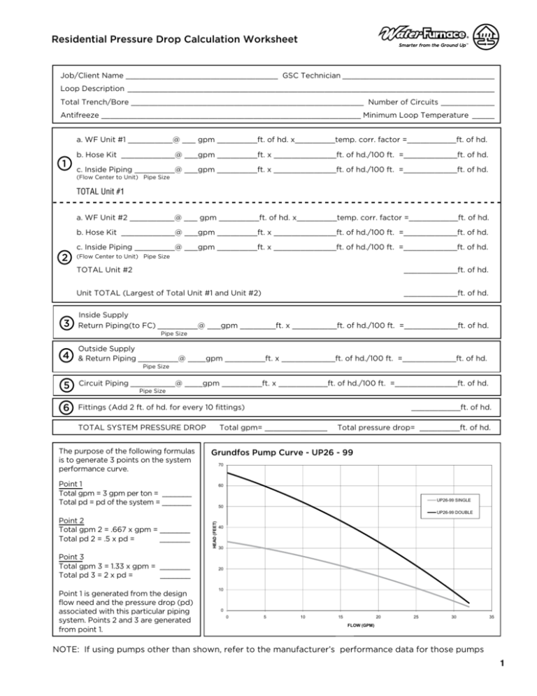
Residential Pressure Drop Calculation Worksheet Job/Client Name __________________________________ GSC Technician __________________________________ Loop Description __________________________________________________________________________________ Total Trench/Bore ____________________________________________________ Number of Circuits ____________ Antifreeze __________________________________________________________ Minimum Loop Temperature _____ a. WF Unit #1 __________@ ___ gpm _________ft. of hd. x_________temp. corr. factor =___________ft. of hd. 1 b. Hose Kit ____________@ ___gpm _________ft. x ______________ft. of hd./100 ft. =____________ft. of hd. c. Inside Piping _________@ ___gpm _________ft. x ______________ft. of hd./100 ft. =____________ft. of hd. (Flow Center to Unit) Pipe Size TOTAL Unit #1 a. WF Unit #2 __________@ ___ gpm _________ft. of hd. x_________temp. corr. factor =___________ft. of hd. b. Hose Kit ____________@ ___gpm _________ft. x ______________ft. of hd./100 ft. =____________ft. of hd. c. Inside Piping _________@ ___gpm _________ft. x ______________ft. of hd./100 ft. =____________ft. of hd. 2 3 (Flow Center to Unit) Pipe Size TOTAL Unit #2 ____________ft. of hd. Unit TOTAL (Largest of Total Unit #1 and Unit #2) ____________ft. of hd. Inside Supply Return Piping(to FC) _________@ ___gpm ________ft. x __________ft. of hd./100 ft. =____________ft. of hd. Pipe Size 4 Outside Supply & Return Piping _________@ ____gpm _________ft. x ____________ft. of hd./100 ft. =____________ft. of hd. Pipe Size 5 Circuit Piping __________@ ____gpm _________ft. x ___________ft. of hd./100 ft. =______________ft. of hd. 6 Fittings (Add 2 ft. of hd. for every 10 fittings) Pipe Size TOTAL SYSTEM PRESSURE DROP The purpose of the following formulas is to generate 3 points on the system performance curve. ___________ft. of hd. Total gpm= ______________ Total pressure drop= _________ft. of hd. Grundfos Pump Curve - UP26 - 99 70 Point 1 Total gpm = 3 gpm per ton = _______ Total pd = pd of the system = _______ 60 UP26-99 SINGLE 50 Point 3 Total gpm 3 = 1.33 x gpm = _______ Total pd 3 = 2 x pd = _______ Point 1 is generated from the design flow need and the pressure drop (pd) associated with this particular piping system. Points 2 and 3 are generated from point 1. HEAD (FEET) UP26-99 DOUBLE Point 2 Total gpm 2 = .667 x gpm = _______ Total pd 2 = .5 x pd = _______ 40 30 20 10 0 0 5 10 15 20 25 30 35 FLOW (GPM) NOTE: If using pumps other than shown, refer to the manufacturer’s performance data . for those pumps 1 RESIDENTIAL EARTH LOOP PRESSURE DROP CALCULATION AND PUMP SIZING MANUAL FCM Flow Center Pump Curve - 2 Pumps Other Pump Performance Curves SuperBrute XL UPS60-150, Two in Series 100 HEAD (FEET) 80 3 60 2 40 1 20 0 0 10 20 30 40 50 60 FLOW (GPM) ©2010 WaterFurnace International, Inc., 9000 Conservation Way, Fort Wayne, IN 46809-9794. WaterFurnace has a policy of continual product research and development and reserves the right to change design and specifications without notice. Manufactured by WaterFurnace International, Inc. 9000 Conservation Way Fort Wayne, IN 46809 www.waterfurnace.com TR1544EW 2 05/10


