5973RH - MS Kennedy
advertisement
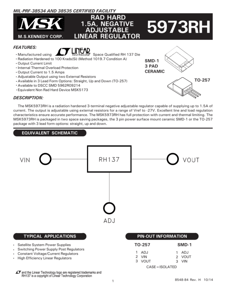
MIL-PRF-38534 AND 38535 CERTIFIED FACILITY M.S.KENNEDY CORP. RAD HARD 1.5A, NEGATIVE ADJUSTABLE LINEAR REGULATOR 5973RH FEATURES: Manufactured using Space Qualified RH 137 Die Radiation Hardened to 100 Krads(Si) (Method 1019.7 Condition A) Output Current Limit Internal Thermal Overload Protection Output Current to 1.5 Amps Adjustable Output using two External Resistors Available in 3 Lead Form Options: Straight, Up and Down (TO-257) Available to DSCC SMD 5962R09214 Equivalent Non Rad Hard Device MSK5173 SMD-1 3 PAD CERAMIC TO-257 DESCRIPTION: The MSK5973RH is a radiation hardened 3-terminal negative adjustable regulator capable of supplying up to 1.5A of current. The output is adjustable using external resistors for a range of Vref to -27V. Excellent line and load regulation characteristics ensure accurate performance. The MSK5973RH has full protection with current and thermal limiting. The MSK5973RH is packaged in two space saving packages, the 3 pin power surface mount ceramic SMD-1 or the TO-257 package with 3 lead form options: straight, up and down. EQUIVALENT SCHEMATIC TYPICAL APPLICATIONS PIN-OUT INFORMATION TO-257 Satellite System Power Supplies Switching Power Supply Post Regulators Constant Voltage/Current Regulators High Efficiency Linear Regulators SMD-1 1 ADJ 2 VIN 3 VOUT 1 ADJ 2 VOUT 3 VIN CASE=ISOLATED 1 8548-84 Rev. H 10/14 ABSOLUTE MAXIMUM RATINGS VIN PD IOUT TJ Input Voltage (VIN-VOUT) Power Dissipation Output Current Junction Temperature ○ ○ ○ ○ ○ ○ ○ ○ ○ ○ ○ ○ ○ ○ ○ ○ ○ ○ ○ ○ ○ ○ ○ ○ TST Storage Temperature Range 11 TLD Lead Temperature Range (10 Seconds) TC Case Operating Temperature MSK5973RH MSK5973(K/H)RH 30VDC Internally Limited 1.5A +150°C ○ ○ 8 ○ ○ ○ ○ ○ ○ ○ ○ ○ ○ ○ ○ ○ ○ ○ ○ ○ ○ ○ ○ ○ ○ ○ ○ ○ ○ ○ ○ ○ ○ ○ ○ ○ ○ ○ ○ ○ ○ ○ ○ ○ ○ ○ ○ ○ ○ ○ -65°C to +150°C ○ ○ ○ ○ ○ ○ ○ ○ 300°C -40°C to +85°C -55°C to +125°C ○ ○ ELECTRICAL SPECIFICATIONS NOTES: 1 Output is decoupled to ground using 10μF low ESR tantalum capacitors and 0.1μF ceramic. 2 Guaranteed by design but not tested. Typical parameters are representative of actual device performance but are for reference only. 3 All output parameters are tested using a low duty cycle pulse to maintain TJ = TC. 4 Industrial grade and devices shall be tested to subgroup 1 unless otherwise specified. 5 Military grade devices ("H" and "K" suffix) shall be 100% tested to subgroups 1,2 and 3. 6 Subgroup 1 TA=TC=+25°C Subgroup 2 TA=TC=+125°C Subgroup 3 TA=TC=-55°C 7 The output current limit function provides protection from transient overloads but it may exceed the maximum continuous rating. Continuous operation in current limit may damage the device. 8 Continuous operation at or above absolute maximum ratings may adversely effect the device performance and/or life cycle. 9 Pre and Post irradiation limits at 25°C, up to 100 Krad TID, are identical unless otherwise specified. 10 Reference DSCC SMD 5962R09214 for electrical specification for devices purchased as such. 11 Internal solder reflow temperature is 180°C, do not exceed. 2 8548-84 Rev. H 10/14 APPLICATION NOTES OUTPUT VOLTAGE LOAD REGULATION The MSK5973RH develops a nominal -1.25V reference voltage between the output and adjustment terminal. With a constant reference voltage drop across program resistor R1, a constant current flows through the output set resistor R2. Since the current from the adjustment terminal represents an error in the programmed output voltage, the MSK5973RH was designed to minimize IADJ and make it very constant with line and load changes. To do this, all quiescent operating current is returned to the output establishing a minimum load current requirement. If there is insufficient load on the output, the output will rise. Figure 1 shows the output voltage calculations. The MSK5973RH is capable of providing extremely good load regulation but a few precautions are needed to obtain maximum performance. The current set resistor connected between the adjustment terminal and the output terminal should be tied directly to the output pin as close to the case of the regulator as possible rather than near the load. This eliminates package pin and trace drops from appearing effectively in series with the reference and degrading regulation. For example, if the regulator is set to -5V with 0.05Ω resistance between the regulator and the current set resistor, the output will droop 225mV at 1A due to package pin and trace resistance. The amount of droop can be calculated as follows: (Vout at 5mA) - (1.250(0.05Ω*IL))*(1+R2/R1). The ground of R2 can be returned near the ground of the load to provide remote ground sensing and improve load regulation. Figure 2A shows the effect of resistance between the regulator and 240Ω set resistor. FIGURE 1 INPUT VOLTAGE FIGURE 2A (Degraded Regulation) The minimum required input voltage for proper operation is VOUT+ Dropout voltage. See typical performance curves for dropout performance. EXTERNAL CAPACITORS Input bypassing with a 1uF tantalum in parallel with a 0.1uF ceramic on the input is suitable in most applications. To maximize transient response and minimize input supply transients more input capacitance can be added. The adjustment terminal can be bypassed to ground on the MSK5973RH to improve ripple rejection. This bypass capacitor prevents ripple from being amplified at higher output voltages. The impedance of the adjust pin capacitor at the ripple frequency should be less than the value of R1. For most application a 10μF bypass capacitor will provide sufficient ripple rejection at any output level. Increases over 10μF do not appreciably improve the ripple rejection at frequencies above 120Hz. Output bypassing with 10μF low ESR tantalum in parallel with a 0.1μF ceramic attached as close to the regulator's output as possible is best. This will effectively lower the regulator output impedance, increase transient response and eliminate any oscillations. Any increase of the load capacitance larger than 10μF will merely improve the loop stability and output impedance. See Figure 3 for typical application schematic. FIGURE 2B (Best Case Regulation) 3 8548-84 Rev. H 10/14 APPLICATION NOTES CONT'D HEAT SINKING PROTECTION DIODES When external capacitors are used with any IC regulator it is sometimes necessary to add protection diodes to prevent the capacitors from discharging through low current points into the regulator. Most 10μF capacitors have low enough internal series resistance to deliver 20A spikes when shorted. Although the surge is short, there is enough energy to stress MSK5973RH. When an output capacitor is connected to a regulator and the input is shorted or crowbarred, the output capacitor will discharge into the output of the regulator. The discharge current depends on the value of the capacitor, the output voltage of the regulator, and the rate of decrease of VIN. Figure 3 shows an MSK5973RH with protection diodes included. D2 is only required if the adjust pin has external capacitance tied to it . To determine if a heat sink is required for your application and if so, what type, refer to the thermal model and governing equation below. Governing Equation: Tj = Pd x (Rθjc + Rθcs + Rθsa) + Ta WHERE Tj = Junction Temperature Pd = Total Power Dissipation Rθjc= Junction to Case Thermal Resistance Rθcs= Case to Heat Sink Thermal Resistance Rθsa = Heat Sink to Ambient Thermal Resistance Tc = Case Temperature Ta = Ambient Temperature Ts = Heat Sink Temperature EXAMPLE: This example demonstrates an analysis with the output set to -10V, where the output current is at 0.5 amp and the input is -15V. Conditions for MSK5973RH: VIN = -15V; Iout = 0.5A 1.) Assume 45° heat spreading model. 2.) Find regulator power dissipation: Pd = (VIN - VOUT)(Iout) Pd = (15V-10V)(0.5A) Pd = 2.5W FIGURE 3 3.) For conservative design, set Tj = +125°C Max. 4.) For this example, worst case Ta= +90°C. 5.) Rθjc = 4.8°C/W from the Electrical Specification Table. 6.) Rθcs= 0.15°C/W for most thermal greases. 7.) Rearrange governing equation to solve for Rθsa: Rθsa=((Tj - Ta)/Pd) - (Rθjc) - (Rθcs) = (125°C-90°C)/2.5W - 4.8°C/W - 0.15°C/ = 9.0°C/W In this case the result is 9.0°C/W. Therefore, a heat sink with a thermal resistance of no more than 9.0°C/W must be used in this application to maintain regulator circuit junction temperature under 125°C. TOTAL DOSE RADIATION TEST PERFORMANCE Radiation performance curves for TID testing have been generated for all radiation testing performed by MS Kennedy. These curves show performance trends throughout the TID test process and is located in the MSK5973RH radiation test report. The complete radiation test report is available in the RAD HARD PRODUCTS section on the MSK website. http://www.mskennedy.com/store.asp?pid=9951&catid=19680 4 8548-84 Rev. H 10/14 TYPICAL PERFORMANCE CURVES 5 8548-84 Rev. H 10/14 MECHANICAL SPECIFICATIONS ESD TRIANGLE INDICATES PIN 1 WEIGHT=3.2 GRAMS TYPICAL ALL DIMENSIONS ARE SPECIFIED IN INCHES ORDERING INFORMATION MSK5973 K RH U LEAD CONFIGURATIONS S= STRAIGHT; U= BENT UP; D= BENT DOWN RADIATION HARDENED SCREENING BLANK= INDUSTRIAL; H=MIL-PRF-38534 CLASS H; K=MIL-PRF-38534 CLASS K GENERAL PART NUMBER The above example is an adjustable Class K regulator with leads bent up. NOTE: See DSCC SMD 5962R09214 for DSCC part number options. 6 8548-84 Rev. H 10/14 MECHANICAL SPECIFICATIONS ALL DIMENSIONS ARE SPECIFIED IN INCHES WEIGHT=2.2 GRAMS TYPICAL ORDERING INFORMATION MSK5973 K RH L 3 PAD CERAMIC SMD-1 PACKAGE RADIATION HARDENED SCREENING BLANK= INDUSTRIAL; H=MIL-PRF-38534 CLASS H; K=MIL-PRF-38534 CLASS K GENERAL PART NUMBER The above example is an adjustable Class K regulator. NOTE: See DSCC SMD 5962R09214 for DSCC part number options. 7 8548-84 Rev. H 10/14 REVISION HISTORY M.S. Kennedy Corp. Phone (315) 701-6751 FAX (315) 701-6752 www.mskennedy.com The information contained herein is believed to be accurate at the time of printing. MSK reserves the right to make changes to its products or specifications without notice, however, and assumes no liability for the use of its products. Please visit our website for the most recent revision of this datasheet. 8 8548-84 Rev. H 10/14
