5.5 Voltage ratings and taps
advertisement
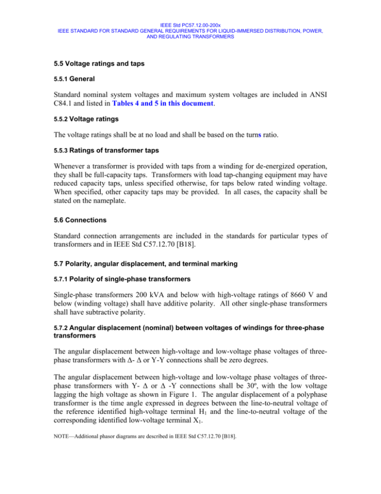
IEEE Std PC57.12.00-200x IEEE STANDARD FOR STANDARD GENERAL REQUIREMENTS FOR LIQUID-IMMERSED DISTRIBUTION, POWER, AND REGULATING TRANSFORMERS 5.5 Voltage ratings and taps 5.5.1 General Standard nominal system voltages and maximum system voltages are included in ANSI C84.1 and listed in Tables 4 and 5 in this document. 5.5.2 Voltage ratings The voltage ratings shall be at no load and shall be based on the turns ratio. 5.5.3 Ratings of transformer taps Whenever a transformer is provided with taps from a winding for de-energized operation, they shall be full-capacity taps. Transformers with load tap-changing equipment may have reduced capacity taps, unless specified otherwise, for taps below rated winding voltage. When specified, other capacity taps may be provided. In all cases, the capacity shall be stated on the nameplate. 5.6 Connections Standard connection arrangements are included in the standards for particular types of transformers and in IEEE Std C57.12.70 [B18]. 5.7 Polarity, angular displacement, and terminal marking 5.7.1 Polarity of single-phase transformers Single-phase transformers 200 kVA and below with high-voltage ratings of 8660 V and below (winding voltage) shall have additive polarity. All other single-phase transformers shall have subtractive polarity. 5.7.2 Angular displacement (nominal) between voltages of windings for three-phase transformers The angular displacement between high-voltage and low-voltage phase voltages of threephase transformers with ∆- ∆ or Y-Y connections shall be zero degrees. The angular displacement between high-voltage and low-voltage phase voltages of threephase transformers with Y- ∆ or ∆ -Y connections shall be 30º, with the low voltage lagging the high voltage as shown in Figure 1. The angular displacement of a polyphase transformer is the time angle expressed in degrees between the line-to-neutral voltage of the reference identified high-voltage terminal H1 and the line-to-neutral voltage of the corresponding identified low-voltage terminal X1. NOTE—Additional phasor diagrams are described in IEEE Std C57.12.70 [B18]. IEEE Std PC57.12.00-200x IEEE STANDARD FOR STANDARD GENERAL REQUIREMENTS FOR LIQUID-IMMERSED DISTRIBUTION, POWER, AND REGULATING TRANSFORMERS H2 H2 X2 X2 X1 H3 H1 X1 X3 H1 ∆ – ∆ CONNECTION X3 H3 Y – ∆ CONNECTION H2 H2 X2 X2 X1 H1 H3 X1 Y – Y CONNECTION X3 H1 H3 X3 ∆ – Y CONNECTION Figure 1 —Phase relation of terminal designation for three-phase transformers 5.7.3 Terminal markings Terminal markings shall be in accordance with IEEE Std C57.12.70 [B18]. 5.8 Impedance The impedance shall be referred to a temperature equal to the sum of the rated average winding temperature rise by resistance, plus 20 ºC. Preferred standard values of impedance are included in the product standards for particular types of transformers. 5.9 Total losses The total losses of a transformer shall be the sum of the no-load losses and the load losses. The losses of cooling fans, oil pumps, space heaters, and other ancillary equipment are not included in the total losses. When specified, power loss data on such ancillary equipment shall be furnished. The standard reference temperature for the load losses of power and distribution transformers shall be 85 ºC. The standard reference temperature for the no-load losses of power and distribution transformers shall be 20 ºC. For Class II transformers, control/auxiliary (cooling) losses shall be measured and recorded. All stages of cooling, pumps, heaters, and all associated control equipment shall be energized, provided these components are integral parts of the transformer. IEEE Std PC57.12.00-200x IEEE STANDARD FOR STANDARD GENERAL REQUIREMENTS FOR LIQUID-IMMERSED DISTRIBUTION, POWER, AND REGULATING TRANSFORMERS 5.10 Insulation levels Transformers shall be designed to provide coordinated low-frequency and impulse insulation levels on line terminals and low-frequency insulation levels on neutral terminals. The primary identity of a set of coordinated levels shall be its Maximum System Voltage and Basic Lightning Impulse Insulation Level (BIL). BIL will be selected dependent on the degree of exposure of the transformer and characteristics of the over-voltage protection system. Power transformers are separated into two different classes as follows: a) Class I power transformers shall include power transformers with high-voltage windings of 69 kV and below. b) Class II power transformers shall include power transformers with high-voltage windings from 115 kV through 765 kV. The following tables on subsequent pages show various system voltages, insulation and test levels for various classes of liquid-immersed power transformers. - Table 4 lists Dielectric Insulation Levels for Distribution and Class I Transformers Table 5 lists Dielectric Insulation Levels for Class II Transformers Table 6 lists the High Frequency Test Levels. Table 4: Distribution and Class I Transformers, voltages in kV Max Sytem Voltage Nominal System Voltage Delta & Fully Applied Test Gr Y Impedance Insulated Gr Y Col 1 Col 2 Col 3 1.5 3.5 6.9 11 17 26 36 48 73 1.2 2.5 5 8.7 15 25 34.5 46 69 10 15 19 26 34 50 70 95 140 1.5 3.5 6.9 11 17 26 36 48 73 Notes: 1 1.2 2.5 5 8.7 15 25 34.5 46 69 10 15 19 26 34 50 70 95 140 2 3 Col 4 Induced Test (phase to ground) 2 times Nominal Voltage Min. Col 6 Col 7 1.4 2.9 5.8 10 17 29 40 53 80 30 45 60 75 95 125 125 200 250 1.4 2.9 5.8 10 17 29 40 53 80 30 45 60 75 95 150 200 200 250 Col 5 Distribution Transformers 10 15 19 26 34 40 50 70 95 Class I Power Transformers 10 10 15 15 19 19 26 26 26 34 26 40 26 50 34 70 34 95 Winding Line-end BIL Alternates Col 8 110 150 150 250 350 45 60 75 95 110 250 350 Col 9 200 Col 10 Neutral BIL GrY Impedance Gr Y Col 11 Col 12 30 45 60 75 75 75 75 95 95 30 45 60 75 75 95 125 150 200 30 45 60 75 75 75 75 95 95 30 45 60 75 75 95 125 150 200 For Nominal System Voltage greater than Maximum System Voltage use the next higher voltage class for applied test levels. Induced tests shall be conducted at 2.0* Nominal voltage. Bold typeface BIL's are standard levels. Y-Y connected transformers using a common solidly grounded neutral may use neutral BIL selected in accordance with the low voltage winding rating. IEEE Std PC57.12.00-200x IEEE STANDARD FOR STANDARD GENERAL REQUIREMENTS FOR LIQUID-IMMERSED DISTRIBUTION, POWER, AND REGULATING TRANSFORMERS Table 5: Max Nominal System System Voltage Voltage Col 1 Col 2 <=17 26 36 48 73 121 145 169 242 362 550 765 800 Notes: 1 2 3 4 Class II Power Transformers, voltages in kV Applied Test Gr Y Impedance Gr Y Insulated Delta & Fully Col 3 Col 4 <=15 25 34.5 46 69 34 50 70 95 140 26 26 26 34 34 115 138 161 230 345 500 735 765 173 207 242 345 518 N/A N/A N/A 34 34 34 34 34 34 34 34 Induced Test (phase to ground) Enhanced One Hour 7200 cy. Col 5 Col 6 Col 7 Low Voltage Windings (69 kV and lower) 26 20 15 34 29 24 50 41 32 70 55 42 95 81 63 High Voltage Windings (115 kV and higher) 95 120 105 95 145 125 140 170 145 140 240 210 140 360 315 140 550 475 140 850 750 140 885 795 Winding Line-end BIL Min. Alternates Neutral BIL Gr Y Impedance Gr Y Col 8 Col 12 Col 13 110 110 110 110 110 110 110 125 150 200 110 110 110 110 110 110 110 110 250 250 350 350 350 350 350 350 Col 9 110 150 200 200 250 250 350 350 450 550 650 900 1425 1950 1950 450 550 650 750 1050 1550 2050 2050 Col 10 550 650 750 825 1175 1675 Col 11 825 900 For Nominal System Voltage greater than Maximum System Voltage use the next higher voltage class for applied test levels. Induced tests shall be conducted at 1.58 * Nominal voltage for one hour and 1.80 * Nominal voltage O for enhanced 7200 cycle tests. Bold typeface BIL's are standard levels. Y-Y connected transformers using a common solidly grounded neutral may use neutral BIL selected in accordance with the low voltage winding rating. For 735kV to 800 kV nominal system voltages, induce test levels do not follow rules in Note 2, and 1950 kV BIL is not a standard IEEE level. 5.10.1 Line terminals 5.10.1.1 Basic lightning impulse insulation level (BIL) A basic lightning impulse insulation level (BIL) from Table 4 shall be assigned to each line terminal of a winding. The associated insulation levels shall be provided regardless of whether tests are or can be performed. 5.10.1.2 Switching impulse insulation level Windings for system voltages 115 kV and above shall be designed for the switching impulse insulation levels (BSL) associated with the assigned BIL as shown in Table 6. In addition, low-voltage windings shall be designed to withstand stresses from switching impulse tests on high-voltage windings regardless of whether or not such tests are specified. 5.10.1.3 Front-of-wave insulation level Front-of-wave insulation levels and tests shall be specified when desired; otherwise, withstand insulation capability is not required. See Annex A for table of historical voltage levels and wave shape characteristics. 5.10.1.4 Wye-winding line terminal Each wye-winding line terminal shall be specified as suitable or unsuitable for ungrounded neutral operation. IEEE Std PC57.12.00-200x IEEE STANDARD FOR STANDARD GENERAL REQUIREMENTS FOR LIQUID-IMMERSED DISTRIBUTION, POWER, AND REGULATING TRANSFORMERS Table 6: High Frequency Test Tables Lightning Chopped Wave Impulse (BIL) kV Crest Min. Time to Flashover, µs kV Crest, 1.2x50 µs 1.1 X BIL Class I & Dist Class II Col 1 Col 2 Col 3 Switching Impulse kV Crest, 0.83 X BIL Col 4 Col 5 30 33 1.0 2.0 See Note 45 50 1.5 2.0 See Note 60 66 1.5 2.0 50 75 83 1.5 2.0 62 95 105 1.8 2.0 79 110 120 2.0 2.0 92 125 138 2.3 2.3 104 150 165 3.0 3.0 125 200 220 3.0 3.0 166 250 275 3.0 3.0 208 350 385 3.0 3.0 291 450 495 N/A 3.0 375 550 605 N/A 3.0 460 650 715 N/A 3.0 540 750 825 N/A 3.0 620 825 900 N/A 3.0 685 900 990 N/A 3.0 745 1050 1155 N/A 3.0 870 1175 1290 N/A 3.0 975 1300 1430 N/A 3.0 1080 1425 1570 N/A 3.0 1180 1550 1705 N/A 3.0 1290 1675 1845 N/A 3.0 1390 1800 1980 N/A 3.0 1500 1950 2145 N/A 3.0 1550 2050 2255 N/A 3.0 1700 Notes: 1. Switching impulse tests are not always possible for low voltage windings. 2. 1550 kV for the 1950 kV BIL is a special application used by a utility that uses transposition to reduce switching impulse levels. Non-transposed lines should use 1620 kV for 1950 kV BIL. 5.10.1.5 Windings that have no terminals brought out Windings that have no terminals brought out shall be capable of withstanding voltages resulting from the various tests that may be applied to other terminals corresponding to their respective BIL. 5.10.2 Neutral terminals 5.10.2.1 Wye connection with an accessible neutral external to the tank A transformer winding designed for wye connection only and with an accessible neutral external to the tank shall be assigned a low-frequency test level for the neutral terminal. This assigned low-frequency test level may be lower than that for line terminals. 5.10.2.2 Neutral terminals that are solidly grounded IEEE Std PC57.12.00-200x IEEE STANDARD FOR STANDARD GENERAL REQUIREMENTS FOR LIQUID-IMMERSED DISTRIBUTION, POWER, AND REGULATING TRANSFORMERS The assigned low-frequency test level for neutral terminals that are solidly grounded directly or through a current transformer shall be not less than that specified in Column 4 of Tables 4 & 5. The assigned low-frequency test level for other cases shall be coordinated with voltages that can occur between the neutral and ground during normal operation or during fault conditions, but shall be not less than those specified in Columns 3, 4, & 5 of Tables 4 & 5. It should be noted that IEEE Std 32 [B13] includes additional information on neutral insulation, application, etc. 5.10.2.3 Specific BIL When specified, neutral terminals shall be designed for a specific BIL instead of a lowfrequency test level. 5.10.2.4 Insulation level of the neutral bushing The insulation level of the neutral end of a winding may differ from the insulation level of the neutral bushing being furnished or of the bushing for which provision for future installation is made. In this case, the dielectric tests on the neutral shall be determined by whichever is lower: the insulation of the neutral end of the winding or the insulation level of the neutral bushing shipped with the transformer. 5.10.2.5 Neutral not brought out of the tank Insulation levels shall not be assigned where the neutral end of the winding is not brought out of the tank through a bushing. In such cases, the neutral end of the winding shall be directly connected to the tank and the tank solidly grounded, unless specified otherwise. 5.10.3 Coordination of insulation levels 5.10.3.1 BIL levels The BIL chosen for each line terminal shall be such that the lightning impulse, choppedwave impulse, and switching impulse insulation levels include a suitable margin in excess of the dielectric stresses to which the terminal will be subjected in actual service. For information on surge arrester characteristics and application, see IEEE Std C62.1 [B44], IEEE Std C62.2 [B45], IEEE Std C62.11 [B46], and IEEE Std C62.22 [B47]. It should be noted that it is recommended that surge-arrester protection be provided for tertiary windings that have terminals brought out. 5.10.3.2 BSL levels A switching surge impulse occurring at one terminal during test or in actual service will be transferred to other winding terminals with a magnitude approximately proportional to the IEEE Std PC57.12.00-200x IEEE STANDARD FOR STANDARD GENERAL REQUIREMENTS FOR LIQUID-IMMERSED DISTRIBUTION, POWER, AND REGULATING TRANSFORMERS turns ratio involved. This interaction should be considered when evaluating surge arrester application, evaluating expected magnitude of surges, and establishing coordinated insulation levels. 5.10.3.3 Grounding considerations (TO BE DELETED) It is necessary to verify the ability of a transformer to withstand temporary overvoltage on unfaulted terminals during single or double line-to-ground faults. In most cases, the low-frequency test is used to provide this verification. The applicable low-frequency test levels are shown in Columns 3, 4, & 5 of Tables 4 & 5. An adequate margin is provided when the low-frequency test coefficient from Table 7 is approximately 1.5 times the coefficient of grounding. The coefficient of grounding is defined in IEEE Std C62.22.3.1.7 [B47], except in this case, a decimal fraction should be used as opposed to a percentage; for example, 0.8 instead of 80%. Caution should be exercised to ensure that the coefficient of grounding has been accurately determined and can be maintained, especially in the case of maximum BIL reductions on delta windings, such as 650 BIL at 230 kV or 350 BIL at 115 kV. Consideration should be given to backfeed in determining if the coefficient of grounding can be maintained. Backfeed would involve energization from the low side of the transformer together with clearing on the high side so that the fault remains on one phase and the system grounding is lost. Under these conditions, a full neutral shift could result on the high-voltage delta winding. In the case of wye windings for Class II transformers, low-frequency test levels and lowfrequency test coefficients in Table 7 are not applicable unless the winding is specified as suitable for application on ungrounded systems. However, when the neutral is solidly grounded to the tank, the neutral end of the winding cannot shift with respect to the tank. Therefore no significant increase in line-terminal-to-ground (tank) voltage during single or double line-to-ground faults should occur provided that proper system grounding practices are employed. For wye windings where Table 7 does not apply and neutral grounding devices significantly affect the coefficient of grounding of the transformer, alternate tests shall be specified to provide the necessary verification. Table 7—Low-frequency test coefficients (TO BE DELETED) Nominal system voltage (kV) Column 1 46 69 115 Basic lightning impulse insulation level (BIL) (kV crest) Column 2 Low-frequency Applied test level (kV rms) Column 3 200 250 250 350 350 450 550 95 95 140 140 173 173 173 Low-frequency test coefficient Column 4 1.967 1.967 1.931 1.931 1.430 1.430 1.430 IEEE Std PC57.12.00-200x IEEE STANDARD FOR STANDARD GENERAL REQUIREMENTS FOR LIQUID-IMMERSED DISTRIBUTION, POWER, AND REGULATING TRANSFORMERS 138 161 230 345 450 550 650 550 650 750 650 750 825 900 900 1050 1175 207 207 207 242 242 242 345 345 345 345 518 518 1.428 1.428 1.428 1.432 1.432 1.432 1.426 1.426 1.426 1.426 1.431 1.431 1.431 518 NOTE 1—The application of this table is covered in Grounding considerations. In particular, the caution regarding application of maximum BIL reductions should be considered. NOTE 2—The low-frequency test coefficient is the ratio between the low-frequency test level and the maximum lineto-line system voltage. 5.10.4 Low-frequency voltage tests on line terminals for distribution transformers and Class I power transformers 5.10.4.1 General Low-frequency test requirements for distribution and Class I power transformers shall be applied-voltage and induced-voltage test levels as specified in Table 4. 5.10.4.2 Applied-Voltage Requirements The applied-voltage test requirements are as follows: a) A voltage to ground (not necessarily to neutral) shall be developed at each terminal in accordance with Columns 3, 4 & 5 of Table 4. For ungraded windings, this voltage shall be maintained throughout the winding. b) A phase-to-phase voltage shall be developed between line terminals of each threephase winding in accordance with Column 3 of Table 4. c) Two times rated turn-to-turn voltage shall be developed in each winding. 5.10.4.3 Exceptions Exceptions to the applied-voltage test requirements are as follows: a) Subject to the limitation that the voltage-to-ground test shall be performed as specified in item a) of 5.10.4.2 on the line terminals of the winding with the lowest ratio of test voltage to minimum turns, the test levels may otherwise be reduced so that none of the three test levels required in 5.10.4.2 need be exceeded to meet the requirements of the other two, or so that no winding need be tested above its specified level to meet the test requirements of another winding. IEEE Std PC57.12.00-200x IEEE STANDARD FOR STANDARD GENERAL REQUIREMENTS FOR LIQUID-IMMERSED DISTRIBUTION, POWER, AND REGULATING TRANSFORMERS b) For delta windings, the voltage-to-ground developed at each terminal shall be in accordance with Table 4; however, voltage within the winding may be reduced to 87% of the voltage developed at the terminals. 5.10.5 Low-frequency voltage tests on line terminals for Class II power transformers 5.10.5.1 Induced-voltage test With the transformer connected and excited as it will be in service, an induced-voltage test shall be performed as indicated in Figure 2, at voltage levels indicated in Columns 6 & 7 of Table 5. Minimum line to ground induced test levels for Class II Power * From Table 5 Enhancement* Voltage Level One Hour Voltage* Level Hold as necessary to check 7200 Cycles One Hour Transformers shall be a multiple of corresponding line to ground nominal system voltage as follows: 1.58 times for one the hour test and 1.8 times for 7200 cycles for the enhancement level test. Figure 2 —Induced voltage test for Class II transformer 5.10.5.2 Applied-voltage test Line terminals of delta windings and all terminals of wye windings for application on ungrounded systems shall receive an applied-voltage test at the levels indicated in Column 3 of Table 5. 5.10.6 Low-frequency voltage test on neutral terminals for all transformers Each neutral terminal shall receive an applied-voltage test at its assigned low-frequency insulation level. 5.10.7 Impulse tests 5.10.7.1 Lightning impulse tests IEEE Std PC57.12.00-200x IEEE STANDARD FOR STANDARD GENERAL REQUIREMENTS FOR LIQUID-IMMERSED DISTRIBUTION, POWER, AND REGULATING TRANSFORMERS The lightning impulse test shall be performed at the specified levels per Columns 1 and 2 of Table 6 for Class II power transformers. When required, lightning impulse tests shall be performed on line and neutral terminals for power transformers. Lightning impulse tests shall not be made on windings that do not have terminals brought out through the tank or cover. Lightning impulse tests are not required on terminals brought out from buried windings in the following cases: a) When a single terminal is brought out for the purpose of grounding the buried winding. b) When two terminals are brought out so that the delta connection may be opened for the purpose of testing the buried winding. c) When temporary connections to terminals of a buried winding are brought out only for the purpose of factory tests. 5.10.7.2 Switching impulse tests When required, switching impulse tests shall be performed. Switching impulse tests on the high-voltage line terminals may overtest or undertest other line terminals depending upon the relative BSL levels, the turns ratios between windings, and test connections. Regardless of this fact, tests on the high-voltage terminals shall be controlling, and a switching impulse test at the level specified in Column 5 of Table 6 shall be applied to the high-voltage terminals. The switching surge insulation of other windings shall be able to withstand voltages resulting from the required switching impulse tests to the high-voltage terminals, even though such voltages on the other windings may exceed their designated BSL listed in Table 6, when applicable. When the application of the switching impulse to the high-voltage terminals result in a voltage on another winding greater than the BSL requirement for that winding in Table 6, no additional test is necessary to demonstrate switching surge insulation withstand capability on that winding. 5.10.7.3 Steep Front Tests Front-of-wave tests (steep wave tests) are no longer recognized as necessary or standard for Distribution, Class I or Class II transformers and are not included in the 2008 revision of C57.12.00. Gapped Silicon Carbide arresters had switching characteristics that closely mimicked steep front-of- wave shapes. Metal Oxide Varister (MOV) Lightning Arresters have clamping characteristics that more nearly emulate Full Wave and Chopped Wave conditions and have replaced silicon carbide arresters, negating the need for front-of-wave testing. Annex I on page XXX includes the last published (C57.12.00-XXXX) Front-ofwave test levels for historical reference IEEE Std PC57.12.00-200x IEEE STANDARD FOR STANDARD GENERAL REQUIREMENTS FOR LIQUID-IMMERSED DISTRIBUTION, POWER, AND REGULATING TRANSFORMERS Annex A (Informative) The following table of Front-of-Wave insulation and test levels has been included for information and historical benefit. The test levels in this table have come from past issues of C57.12.00, dating back to earlier than 1965 through 1980 issues. Front-of-Wave tests for 30 kV BIL was discontinued prior to the1965 issue. Front-of-Wave tests for 45-75 kV BIL were discontinued by 1980. The Front Of Wave Test, Voltages in kV : Note that this test is no longer specified but is documented for historical purposes Lightning Front Of Wave Impulse (BIL) kV Crest Min. Time to Min. effective kV Crest, 1.2x50 µs Flashover, µs Rate Of Rise, (kV/ µs) Col 1 Col 2 Col 3 Col 4 30 45 60 75 95 110 125 150 200 250 350 450 550 650 750 825 900 1050 1175 1300 1550 75 75 125 165 165 195 220 260 345 435 580 710 825 960 1070 1150 1240 1400 1530 - 0.5 0.5 0.5 0.5 0.5 0.5 0.5 0.5 0.5 0.5 0.58 0.71 0.825 0.96 1.07 1.15 1.24 1.4 1.53 - 125 125 210 210 275 430 430 430 575 725 850 850 850 850 850 850 850 850 850 -
