The 8255A programmable peripheral interface:
advertisement
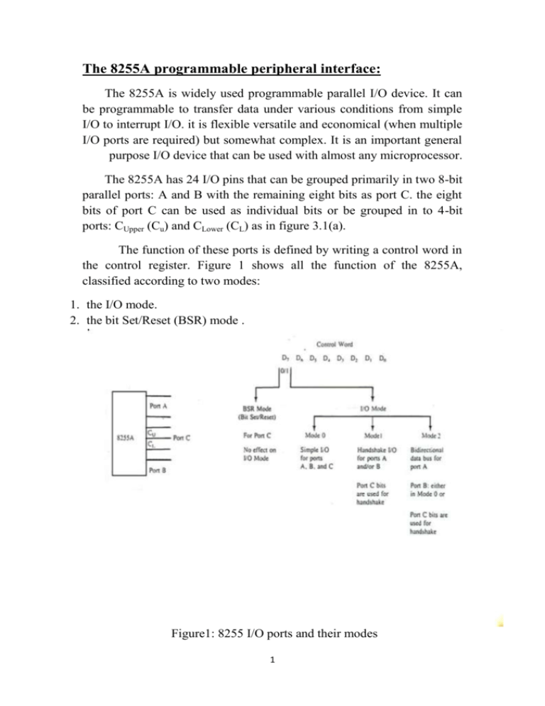
The 8255A programmable peripheral interface: The 8255A is widely used programmable parallel I/O device. It can be programmable to transfer data under various conditions from simple I/O to interrupt I/O. it is flexible versatile and economical (when multiple I/O ports are required) but somewhat complex. It is an important general purpose I/O device that can be used with almost any microprocessor. The 8255A has 24 I/O pins that can be grouped primarily in two 8-bit parallel ports: A and B with the remaining eight bits as port C. the eight bits of port C can be used as individual bits or be grouped in to 4-bit ports: CUpper (Cu) and CLower (CL) as in figure 3.1(a). The function of these ports is defined by writing a control word in the control register. Figure 1 shows all the function of the 8255A, classified according to two modes: 1. the I/O mode. 2. the bit Set/Reset (BSR) mode . Figure1: 8255 I/O ports and their modes 1 The BSR mode is used to set or reset the bits in port C. The I/O mode is further divided into three modes: mode 0, mode 1, and Mode 2. In mode 0, all port function as simple I/O ports. Mode 1 is a handshake Mode whereby ports A and/or B use bits from port C as handshake signals. In the handshake mode, two types of I/O data transfer can be implemented: status check and interrupt. In mode 2, port A can be set up for bidirectional data transfer using handshake signals from port C, and port B can Be set up either in mode or Mode 1. 2 Control word: Figure 2 shows a register called the control register. The control of this register, called the control word, specify an I/O function for each port this register can be. Figure 2:8225A an I/O ports 2 Figure 3:8255A chip select logic (a) and I/O port addresses (b) 3 Accessed to write a control word when A0 and A1 are at logic1 , the register is not accessible for a read operation. Bit D7 of the control register either specifies the I/O function or the bit Set/Reset function, as classified in figure 1. If bit D7=0, bits D6-D0 determine I/O function in various mode, as shown in figure 4.if bit D7=0 port C operates in the bit Set/Reset (BSR) mode. The BSR control word does not affect the function of port A and B To communicate with peripherals through the 8255A, three steps are necessary: 1. Determine the addresses of ports A, B, and C and of the control register according to the Chip select logic and address lines A0 and A1. 2. Write a control word in the control register. 3. Write I/O instructions to communicate with peripherals through ports A, B, and C Figure4:8255A control word format for I/O mode 4
