COMSOL Tutorial 3 - Department of Mechanical Engineering
advertisement
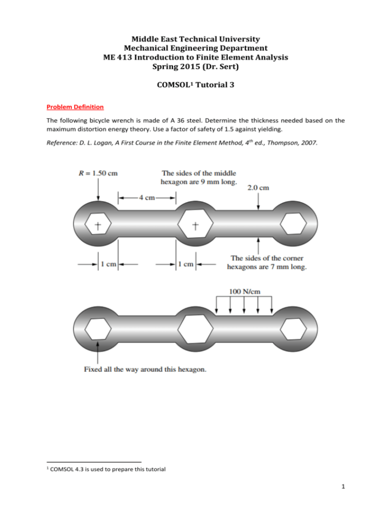
Middle East Technical University Mechanical Engineering Department ME 413 Introduction to Finite Element Analysis Spring 2015 (Dr. Sert) COMSOL1 Tutorial 3 Problem Definition The following bicycle wrench is made of A 36 steel. Determine the thickness needed based on the maximum distortion energy theory. Use a factor of safety of 1.5 against yielding. Reference: D. L. Logan, A First Course in the Finite Element Method, 4th ed., Thompson, 2007. 1 COMSOL 4.3 is used to prepare this tutorial 1 1. Start COMSOL. Select “2D“ and click the “Next” arrow. Select “Structural Mechanics -> Solid Mechanics” and click the “Next” arrow. Select “Stationary” and click the “Finish” button. 2a. In the “Model Builder” (MB) tab right click “Geometry 1” and select “Circle”. Set “Radius” to 0.015 m. Keep the center at the origin. Click “Build Selected”. 2b. Repeat step 2a to create another circle with radius 0.015 m and center at (0.06, 0). To see both circles press “Zoom Extents” button of the “Graphics” tab. 2c. Repeat step 2b to create a third circle with radius 0.015 m and center at (0.12, 0). 3a. Draw the rectangular region that combines the first two circles. Let the rectangle overlap with the circles so that a union operation can be performed later. In the “Model Builder” (MB) tab right click “Geometry 1” and select “Rectangle”. Set “Width” to 0.042 m, “Height” to 0.02 m and locate its base corner at (0.009, -0.01). Click “Build Selected”. 3b. Repeat step 3a to draw the rectangle between the 2nd and 3rd circles. Set “Width” to 0.042 m, “Height” to 0.02 m and locate its base corner at (0.069, -0.01). 2 At this point the Graphics tab should look like this. Press the “Zoom Extents” button to see all five parts built. 3 4. To combine these five parts into a single object, right click “Graphics 1” in the MB tab and select “Boolean Operations -> Union”. Select all 5 objects and add them to “Input objects”. Deselect “Keep interior boundaries”. Click “Build Selected”. 4 5a. To draw the first hexagon right click “Geometry 1” in the MB tab and select “Polygon”. Change “Data source” to “Table”. Enter the coordinates of 6 corners of the hexagon. Press “Build Selected”. 5b. Repeat Step 5a to draw the other hexagons with the following coordinates. 5 Graphics window should look like this. 6 6. To set the hexagons as holes, right click “Geometry 1” in the MB tab and select “Boolean Operations -> Difference”. Add the outer body to “Objects to add”. Add the three hexagons to “Objects to subtract”. Press “Build Selected”. 7 7. Right click “Materials” in the MB tab and select “Material”. Enter the following properties. 8 8. Select “Solid Mechanics” in the MB tab. Set “2D Approximation” to “Plane stress”. Set “Thickness” to 0.01 m. This is an initial value. We’ll change it later to find the smallest allowable thickness to prevent yielding. 9 9a. To avoid the motion of the first hexagon, right click “Solid Mechanics” in the MB tab and select “Fixed Constraint”. Select 6 edges of the first hexagon. 10 9b. To apply the force, right click “Solid Mechanics” in the MB tab and select “Boundary Load”. Select the part of the wrench where the load is applied. Set “Load type” to “Load defined as force per unit length”. Set 𝑦-component of the force to “-40000 N/m”. Minus sign indicates a force in –𝑦 direction. 11 10. Select “Mesh 1” in the MB tab. Keep the default settings, i.e. “Physics-controlled mesh” and “Normal”. Press the “Build All” button. 12 11. Right click “Study 1” in the MB tab and select “Compute”. Solution will be done in a few seconds and following result will be displayed. According to this contour plot, the maximum von Misses stress is 214 MPa, which is larger than the limiting value of Maximum allowable von Mises stress = Yield strength 250 MPa = = 167 MPa Factor of safety 1.5 13 12. In the previous graph, deflections are automatically scaled up to see them better. To see the actual deflected shape, in the MB tab select “Results -> Stress -> Surface 1 -> Deformation”. Check the “Scale factor” box and set its value to 1. Press the “Plot” button. Now you need to zoom in enough to see the deflections. 14 13. The maximum von Misses stress value read from the legend of the contour plot may be misleading. It is better to directly ask for it. Right click “Results -> Derived Values” in MB tab and select “Maximum -> Surface Maximum”. Set “Selection” to “All domains”. Change “Expression” to “solid.mises”. You can make this change by pressing “Replace expression” button and choosing the parameter that you are interested in, in this case “von Mises stress”. Press the “Evaluate” button. The maximum von Mises stress value will be displayed in the Results tab as 225 MPa, which is a little bit larger than the value read from the contour plot legend. 15 14a. The first solution was performed using the “Normal” mesh. To see the effect of mesh on the results go to “Mesh 1” in the MB tab, change “Element size” to “Finer” and rebuild the mesh. Compute the solution. Evaluate the maximum von Mises stress. It is increased to 260 MPa. 14b. Refine the mesh further by selecting “Element size” as “Extremely fine”. Rebuild the mesh. Compute the solution. Evaluate the maximum von Mises stress. It is increased to 328 MPa. IMPORTANT: Unfortunately, there will be no end to this increase. For a solution with perfect elasticity assumption, at the sharp corners known as re-entrant corners, stresses will increase unboundedly as the mesh is refined. This is known as stress singularity. Although deformation results may be physical, maximum stress values are misleading. To avoid this we have two options Change the physics of the problem to allow local plastic deformation at sharp corners. Due to yielding at these corners stress will be distributed to the near vicinity of the corner. Modify sharp corners by inserting fillets. In real life, corners will have a certain amount of roundness anyway. 16 15. To smooth out sharp corners, right click “Geometry 1” in the MB tab and select “Fillet”. Select the following 24 corners and set the “Radius” to 0.002 m. Press “Build Selected”. New nodes and fillets will be introduced. 17 16a. Re-build the mesh using “Coarser” element size. It’ll have small elements around the critical corners due to the fine geometric details of the fillets. Compute the solution. Evaluate the maximum von Mises stress. It is 289 MPa. 16b. Re-build the mesh as “Normal”. Compute the solution. Evaluate the maximum von Mises stress. It is increased to 301 MPa. 16c. Re-build the mesh as “Finer”. Note that “Fine” and “Normal” meshes turn out to be the same. Compute the solution. Evaluate the maximum von Mises stress. It is increased to 302 MPa. 16d. Re-build the mesh as “Extra fine”. Compute the solution. Evaluate the maximum von Mises stress. It is increased to 302 MPa. 16e. Re-build the mesh as “Extremely fine”. Compute the solution. Evaluate the maximum von Mises stress. It is increased to 302 MPa. 18 Results of Step 16 are summarized below. Table 1. Maximum von Mises stress (solid.mises) with 2 mm fillets obtained with different meshes Number of elements Maximum von Mises stress [MPa] Coarser 1362 289 Normal 3504 301 Finer 4508 302 Extra fine 5734 302 Extremely fine 13764 302 CONCLUSIONS: 1. By introducing fillets, unbounded growth of stress at the corners upon mesh refinement is avoided and a convergent result is obtained with a maximum von Mises stress value of 302 MPa. This is larger than the allowable value of 167 MPa. By increasing the thickness of the wrench (In the MB tab, select “Solid Mechanics” and change the thickness value) maximum stress can be reduced. For this plane stress problem, the relation between the thickness and stress is inverse, i.e. if we double the thickness, stresses will reduce by a factor of 2. Therefore the limiting thickness value can be obtained as Max. stress for 1 cm thickness 302 MPa (1 cm) = (1 cm) = 1.8 cm Allowable stress 167 MPa 2. Fillet radius has an effect on stress levels. If it is reduced to 1 mm, maximum von Mises stress converges to a value of 370 MPa (~20 % increase). 3. As shown below, unlike stresses, displacements are not effected by mesh refinement or by the introduction of fillets. Table 2. Maximum displacement (solid.disp) for different simulations No fillets 2 mm Fillets Mesh Maximum displacement [mm] Mesh Maximum displacement [mm] Normal 0.45 Normal 0.44 Finer 0.45 Finer 0.44 Extremely fine 0.45 Extremely fine 0.44 19 NOTES: 1. After generating fillets, if you want to study the “No fillet” case again, do NOT delete fillets. Simply disable them by right clicking “Geometry 1 -> Fillet 1” and selecting “Disable”. Later you can “Enable” them again. 2. To probe the stress values at any point on the wrench, select “Results -> Stress” in the MB tab and click anywhere on the wrench. Coordinates and the von Mises stress value of the clicked point will be shown in the “Results” tab. 3. In generating the mesh it is possible to set local size controls. Select “Mesh 1” in the MB tab. Set “Sequence type” to “User-controlled mesh”. In the MB tab, “Free Triangular 1” will be created. Right click it and select “Size”. Set “Geometric entity level” to “Point”. Select the points around which you want refinement. Below, only 2 points are selected. Check “Custom” for “Element Size”. Check “Maximum element size” and set its value to 0.001 m. Press “Build Selected”. 20 Following mesh, refined around the selected corners (shown in blue) will be generated. If necessary, it is possible to control mesh sizing in much more detail. 21
