Objectives
Implement Spanning
Tree Protocols
LAN Switching and Wireless – Chapter 5
Explain the role of redundancy in a converged
network
Summarize how STP works to eliminate Layer 2 loops
in a converged network
Explain how the STP algorithm uses three steps to
converge on a loop-free topology
Implement rapid per VLAN spanning tree (rapid
PVST+) in a LAN to prevent loops between redundant
switches.
2
ITE I Chapter 6
© 2006 Cisco Systems, Inc. All rights reserved.
Cisco Public
1
The Role of Redundancy in a Switched
Network
Layer 2 Loops
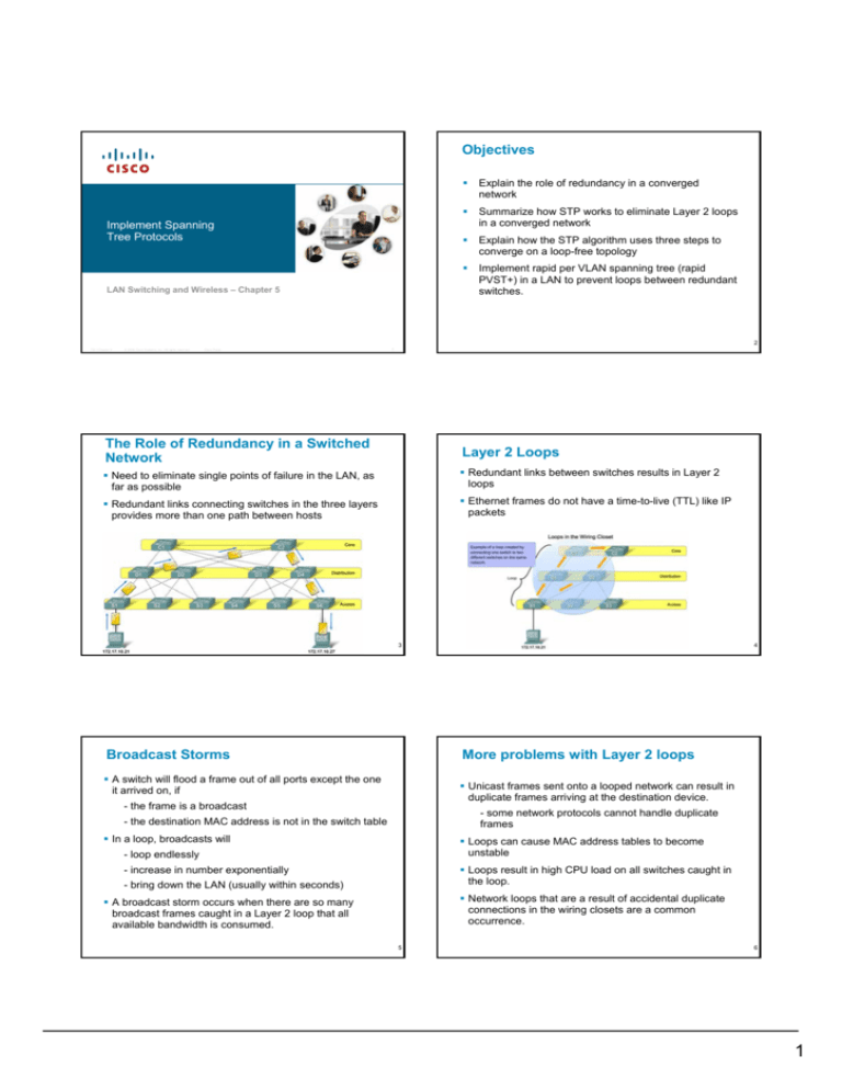
Need to eliminate single points of failure in the LAN, as
far as possible
Redundant links between switches results in Layer 2
loops
Redundant links connecting switches in the three layers
provides more than one path between hosts
Ethernet frames do not have a time-to-live (TTL) like IP
packets
3
Broadcast Storms
4
More problems with Layer 2 loops
A switch will flood a frame out of all ports except the one
it arrived on, if
Unicast frames sent onto a looped network can result in
duplicate frames arriving at the destination device.
- the frame is a broadcast
- some network protocols cannot handle duplicate
frames
- the destination MAC address is not in the switch table
In a loop, broadcasts will
Loops can cause MAC address tables to become
unstable
- loop endlessly
- increase in number exponentially
Loops result in high CPU load on all switches caught in
the loop.
- bring down the LAN (usually within seconds)
Network loops that are a result of accidental duplicate
connections in the wiring closets are a common
occurrence.
A broadcast storm occurs when there are so many
broadcast frames caught in a Layer 2 loop that all
available bandwidth is consumed.
5
6
1
Spanning Tree Protocol (STP)
The Spanning Tree Topology
STP prevents Layer 2 loops.
Nodes are connected as a tree if
STP runs on all Layer 2 switches and bridges by default
straight out of the box
- each node has one and only
one parent node
STP ensures that there is only one logical path
between all destinations on the network by intentionally
blocking redundant paths that could cause a loop
- except for the root node
Root node
Change a general structure into a
tree structure by removing some
of the links
Switches and bridges running STP cooperate to
produce a logical loop-free layer 2 topology
A spanning tree means all nodes
remain connected
If a link goes down, the STP algorithm will automatically
be run again to determine a new spanning tree
topology. Hence, redundancy is maintained.
A tree structure will not contain
any loops
7
STP in action
8
BPDUs
STP puts port F0/2 on S3 into blocking mode, thus
removing a loop
Switches running STP need to cooperate with each
other
Now there is only one path between any source and
destination device
They use Bridge Protocol Data Units (BPDUs) to
exchange messages
An Ethernet frame encapsulates the BPDU
Uses an Ethernet multicast address for the spanningtree group
Each BPDU contains a BID number that identifies the
switch that sent the BPDU
9
The BPDU Fields
10
Bridge ID (BID)
Each switch has a unique Bridge ID number (BID) made
up of:
Bridge priority – 16-bit customizable, default 32768
MAC address – guarantees uniqueness
The BID identifies the switch and is used in elections.
The admin can determine the outcome of an election by
setting the value of the Bridge Priority field
11
12
2
STP Convergence Steps
When bootup has completed, each switch determines
the logical spanning tree topology by running the
Spanning Tree Algorithm (STA)
The STP Algorithm uses three steps to converge on a
loop-free topology:
Step 1: Elect a Root Bridge
Step 2: Elect the Root Ports
Step 3: Elect the Designated and Non-Designated
ports
13
Step 1: Elect a Root Bridge
14
Port Roles
Each switch port connecting to another switch (i.e. that
receives BPDUs) is assigned one of the following port roles
by the STA:
The first step is to elect a Root Bridge. The switch with
the lowest BID wins.
All switches continuously transmit BPDUs out of all ports
Root port
Each BPDU contains the BID of the sender and the BID
of the current Root Bridge
This is the port closest to the Root Bridge
This port will forward frames
Each switch initially assumes that it is the Root Bridge
Designated port
When a BPDU is received with a lower Root Bridge BID, it
replaces the current one in future BPDU transmissions.
If two or more switches connect to the same segment,
only one will be the designated port
After no more than 20 seconds, a single Root Bridge will
have been identified by all switches.
This port will forward frames
Non-designated port
15
The port is in blocking mode; it will not forward user
frames
16
Step 2: Elect Root Ports
All of the Root Bridge ports become Designated Ports
A Root Port exists on each non-root bridge. It is the
switch port with the best path to the Root Bridge
Choosing the Root Port:
- The Root Bridge continues to send BPDUs which
are relayed through the network by the other
switches
- As each BPDU is sent out of a port, the cost field is
updated, in accordance with the port bandwidth
- As a switch receives BPDUs from the Root Bridge,
the one with the lowest cost identifies the Root Port
- Each switch will have one and only one Root Port
17
18
3
Step 3: Elect Designated and Non-Designated
Ports
The remaining ports on a switch which connect to other
switches will be either Designated Ports or Nondesignated Ports
If two switches connect to the same segment, the port
on the switch with the lowest BID becomes a
Designated Port. The port on the other switch
becomes a Non-designated Port.
Designated Ports will forward user frames.
Non-designated Ports will be blocked
Result is each segment will have only one switch
forwarding frames onto it
19
20
Port States
While the STA is running, each switch port will be in one of
these port states:
Blocking - A non-designated port; does not participate in
frame forwarding. Receives BPDU frames only
Listening - STP has determined that the port can
participate in frame forwarding. Receives BPDU frames
and also transmits its own BPDU frames
Learning - The port prepares to participate in frame
forwarding and begins to populate the MAC address table.
Forwarding - The port is part of the active topology and
forwards frames, sends and receives BPDU frames.
Disabled - The switch port is administratively disabled.
21
Port States
22
BPDU Timers
The spanning tree is determined immediately after a
switch has finished booting up.
Network diameter is the number of devices that a packet
has to cross before it reaches its destination.
All ports are initially put in Blocking mode
Default convergence times are based on a seven-switch
diameter network
(LEDs on switch port will be amber)
When the STA has completed, each port will be in either
Blocking mode or Forwarding mode
A port that becomes part of the final spanning tree
topology will transition between modes in this order:
Hello time – Default 2 secs.
Forward delay – time spent in listening and learning
state. Default 15 secs each.
Maximum age – Default 20 secs.
1. Blocking
2. Listening
Optimize timers by reconfiguring the network diameter, not
the BPDU timers.
3. Learning
On root bridge only:
4. Forwarding
23
spanning-tree vlan vlan-id root primary diameter
value
24
4
Summary Spanning Tree Protocol (STP)
STP Variants
Standard IEEE 802.1D STP
STP’s lengthy convergence time (50 seconds) facilitated
the development of:
Only one spanning tree instance in a network (i.e.
broadcast domain).
RSTP
IEEE standard (IEEE 802.1w)
convergence time is slightly over 6 seconds
BID is 2-byte bridge priority + MAC address.
Only one Root Bridge elected in the network.
Each non-root switch has one Root Port – shortest path
to the Root Bridge
Each segment is connected by no more than one
Designated Port
All other ports on a switch are non-designated ports
and are in blocking mode.
Convergence time is 50 seconds
25
PVST+ Feature: PortFast
Rapid PVST+
Cisco proprietary technology
This is the preferred STP on a Cisco switched
network
Adds VLAN support to RSTP
Separate Root Bridge for each instance means better
redundancy.
Can load balance VLANs on trunks
26
PVST+: Bridge ID (BID)
PortFast is a Cisco proprietary technology.
When an access switch port is configured with PortFast
it transitions from blocking to forwarding state
immediately.
Use only on access ports connected to a single
workstation,etc. to allow those devices to connect to the
network immediately.
The Bridge ID number (BID) is made up of three fields:
Bridge priority – 4-bit customizable
Extended System ID – 12-bit VLAN ID number
MAC address – guarantees uniqueness
If a port configured with PortFast receives a BPDU
frame, spanning tree can put the port into the blocking
state using a feature called BPDU guard.
The first two fields are displayed as a single number.
PortFast technology can be used to support DHCP.
Therefore changing the Bridge Priority changes the
number in steps of 4096
27
Default is 32769 – i.e. 32768 + VLAN 1
28
RSTP (IEEE 802.1w)
RSTP - speeds the recalculation of the spanning tree
when the Layer 2 network topology changes.
RSTP supersedes STP (802.1D) while retaining
backward compatibility.
RSTP keeps the same BPDU format with version set to
2.
Edge port - corresponds to the Cisco PortFast feature
Non-edge ports are categorized into two link types,
point-to-point and shared.
Possible RSTP port states: discarding, learning, and
forwarding
29
5


