Networking - CS-People by full name
advertisement
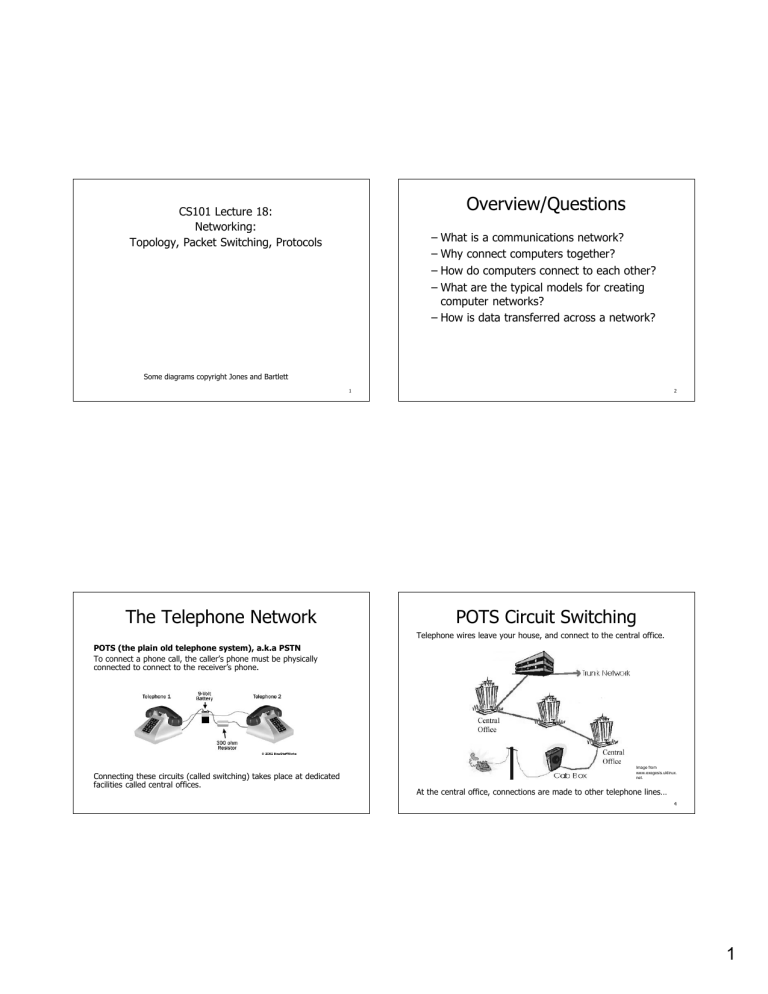
Overview/Questions CS101 Lecture 18: Networking: Topology, Packet Switching, Protocols ± What is a communications network? ± Why connect computers together? ± How do computers connect to each other? ± What are the typical models for creating computer networks? ± How is data transferred across a network? Some diagrams copyright Jones and Bartlett 1 The Telephone Network 2 POTS Circuit Switching Telephone wires leave your house, and connect to the central office. office. POTS (the plain old telephone system), a.k.a PSTN To connect a phone call, the caller¶s phone must be physically connected to connect to the receiver¶s phone. Connecting these circuits (called switching) takes place at dedicated facilities called central offices. offices. Image from www.exegesis.uklinux. net. At the central office, connections are made to other telephone lines« lines« 4 1 POTS Circuit Switching Computer Networking Telephone operators used to actually switch wires to connect the calls. Computer Network A collection of computing devices connected in order to communicate and share resources. Connections between computing devices can be physical using wires or cables, or wireless using radio waves or infrared signals. Why connect computers together? In the PSTN, this connection (called switching) is done electronically. electronically. 5 Networking Networking Terms Computer networks have opened up an entire frontier in the world of computing called the client/server model. Figure 15.1 Client/Server interaction 6 Client A computer which uses (consumes) resources from the network. Server A computer that stores and manages files or applications for multiple users on a network. Example: Web Server A computer dedicated to responding to requests (from the browser client) for web pages. 7 8 2 Networking Terms Network Nodes Bandwidth (data transfer rate) The speed at which data is transferred over a telecommunications link on a network. Bandwidth is measured in bits per second (bps/Kbps/Mbps). A network node is any device on a network: ± Computer (desktop, laptop, PDA, etc.) ± Server (web server, mail server, etc. ) ± Router (device which directs traffic) ± Firewall (access control device) Why is bandwidth such a big deal? 9 10 Network Interface Controller Network Topologies Each node has a network interface controller (NIC) connected to its circuit board. LocalLocal-area Network (LAN) A network that connects a relatively small number of machines in a relatively close geographical area. The CPU treats the NIC as an input/output device. Network Topology Describes the physical wiring plan for connections between nodes on a network. Also describes how messages are sent between nodes. It communicates by reading or writing bytes of data to the NIC. Each NIC has a unique Media Access Control (MAC) address, which distinguishes it from all other NICs. NICs. 11 12 3 Ring Network Topology A ring network connects all nodes in a closed loop on which messages travel in one direction. A star network centers around one node to which all others are connected and through which all messages are sent. How many hops? Complexity? How many hops? Complexity? Bus Network Topology On a bus network nodes are connected to a single communication line that carries messages in both directions. How many hops? Complexity? Star Network Topology Ethernet The industry standard bus technology for locallocal-area networks. Types of Networks WideWide-area network (WAN) A network that connects locallocal-area networks over a potentially large geographic distance. MetropolitanMetropolitan-area network (MAN) The communication infrastructures that have been developed in and around large cities or campuses. Gateway/Router One particular computer on a LAN which coordinates/directs all communication going between that LAN and other networks. 16 4 Circuit Switched Network Creating a WAN Computers can be connected over a circuit switched network (e.g. phone lines), creating a circuit between the source and destination. LANs separated by a great distance are connected by High speed communication links to create a WAN. A Switched Circuit connects devices A and B. Image from www.tcpipguide.com. 17 Data Transmissions Bursty Transmissions Computers send data in irregular bursts ± a bunch of data at one shot, and then nothing for a long time in between messages. Using a switched network connection is wasteful ± the wires must be connected even if no data is being sent! Packet Switching Packet A unit of data sent across a network. Packet switching Messages are divided into fixedfixed-sized, numbered packets. Packets are individually routed to their destination, then reassembled into messages. Router A network device that directs a packet between networks toward its final destination. 5 Packet Switching Network Packet Switching Nodes send packets of data along routes to a destination, without a dedicated circuit. Image from www.tcpipguide.com. Figure 15.4 Messages sent by packet switching 21 Benefits of Packet Switching Communication links between nodes are only allocated while transmitting each packet. - Longer messages require multiple packets, but the link is not dedicated when there is no data to send. Packet switching enables data to travel from its source to its destination over any number of possible routes. - Increases reliability of message delivery. Packets (even in the same transmission) can take different routes. 22 Network Protocols Protocol A set of rules that defines how data is formatted and processed on a network. Open System A system which is based on published standards for how protocols should work. Open systems enable interoperability of network software and hardware components from different vendors. 6 The OSI SevenSeven-Layer Model for Networking Applications Open Systems Interconnection Open Systems Interconnection (OSI) Reference Model A sevenseven-layer logical break down of network interaction to facilitate communication standards. Each layer deals with a particular aspect of network communication. Network protocols are usually specific to one layer of this model. Figure 15.5 The layers of the OSI Reference Model 25 Network Protocols Layer Name Layer Functions Application Specifies the syntax to be used between sending and receiving processes. Presentation Converts between native and network data representations, allowing machines of different architectures to communicate in a common "network"network-neutral" format. Session Handles login, restart, check pointing, and other session state maintenance issues. Transport Provides reliability of packet delivery where appropriate. Network Handles pointpoint-toto-point routing across the network, fragments data into chunks appropriate to datalink technology to be used, and reassembles on receipt. Datalink Takes networknetwork-layer datagrams and frames them for transmission. Physical Converts datalink frames into bit streams for transmission over some physical medium. 26 TCP/IP Suite Internet Protocol (IP) Software that deals with the routing of packets through the maze of interconnected networks to their final destination. Protocol Stack Network protocols are layered such that each protocol relies on the protocols that underlie it. ± tracks each packet¶s source, destination, packet size, and maximum number of hops. IP does not guarantee delivery of packets. Rather, IP is a bestbest-effort protocol. Figure 15.6 Layering of key network protocols (diagram showing layers 3-4-5) 27 28 7 TCP/IP Suite HighHigh-Level Protocols Transmission Control Protocol (TCP) Software that breaks messages into packets, hands them off to the IP software for delivery, and then orders and reassembles the packets at their destination. Port A numeric designation that corresponds to a particular high-level protocol ± TCP guarantees delivery of packets. User Datagram Protocol (UDP) An alternative to TCP that is faster but less reliable. Figure 15.7 Some high-level protocols which rely upon TCP/IP, and the ports they use. ± UDP does not guarantee delivery of packets. 29 30 Summary ± Networks enable the clientclient-server model for sharing data and applications between users. ± Topology describes the physical layout of a network as well as the number of hops for message transmission. ± Packet switching makes most efficient use of network transmission lines, and provides multiple routes from source to destination. ± Protocols describe how data is exchanged over a network. 31 8


