Calipers - mitutoyo.co.jp
advertisement
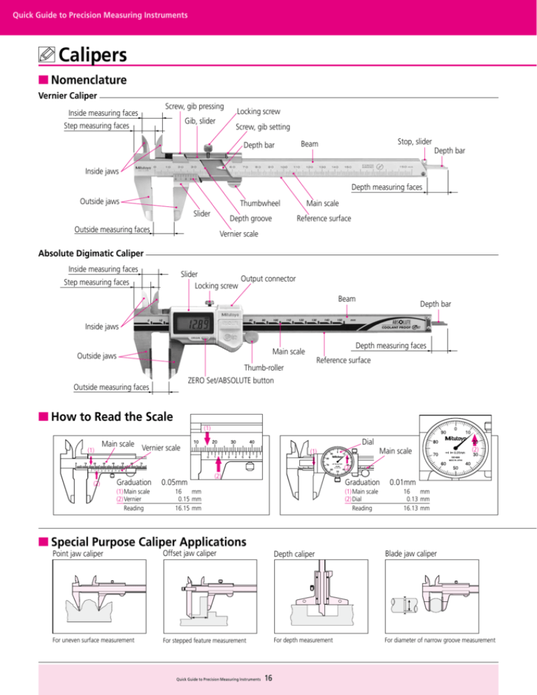
Quick Guide to Precision Measuring Instruments Calipers ■Nomenclature Vernier Caliper Screw, gib pressing Inside measuring faces Gib, slider Step measuring faces Locking screw Screw, gib setting Depth bar Stop, slider Beam Depth bar Inside jaws Depth measuring faces Outside jaws Thumbwheel Slider Depth groove Outside measuring faces Main scale Reference surface Vernier scale Absolute Digimatic Caliper Inside measuring faces Slider Output connector Locking screw Step measuring faces Beam Depth bar Inside jaws Depth measuring faces Main scale Outside jaws Reference surface Thumb-roller ZERO Set/ABSOLUTE button Outside measuring faces ■How to Read the Scale (1) (1) Main scale Dial Vernier scale (1) Main scale (2) (2) (2) Graduation 0.05mm (1)Main scale (2)Vernier Reading (2) Graduation 0.01mm 16 mm 0.15mm 16.15mm (1)Main scale (2)Dial Reading ■Special Purpose Caliper Applications 16 mm 0.13mm 16.13mm Point jaw caliper Offset jaw caliper Depth caliper Blade jaw caliper For uneven surface measurement For stepped feature measurement For depth measurement For diameter of narrow groove measurement Quick Guide to Precision Measuring Instruments 16 ■Types of Vernier Scale ■Moving Jaw Tilt Error The Vernier scale is attached to the caliper’s slider and each division on this scale is made 0.05mm shorter than one main scale division of 1 mm. This means that, as the caliper jaws open, each successive movement of 0.05mm brings the succeeding vernier scale line into coincidence with a main scale line and so indicates the number of 0.05mm units to be counted (although for convenience the scale is numbered in fractions of a mm). Alternatively, one vernier division may be made 0.05mm shorter than two divisions of the main scale to make a long vernier scale. This makes the scale easier to read but the principle, and resolution, is still the same. If the moving jaw becomes tilted out of parallel with the fixed jaw, either through excessive force being used on the slider or lack of straightness in the reference edge of the beam, a measurement error will occur as shown in the figure. This error may be substantial due to the fact that a caliper does not conform to Abbe’s Principle. h h θ a f=hθ=h·a/ℓ f ●Standard Vernier scale (resolution 0.05mm) Example: Assume that the error slope of the jaws due to tilt of the slider is 0.01mm in 50mm and the outside measuring jaws are 40mm deep, then the error (at the jaw tip) is calculated as (40/50)x0.01mm = 0.008mm. If the guide face is worn then an error may be present even using the correct measuring force. Reading 1.45mm ●Long Vernier scale (resolution 0.05mm) ■About Long Calipers Steel rules are commonly used to roughly measure large workpieces but if a little more accuracy is needed then a long caliper is suitable for the job. A long caliper is very convenient for its user friendliness but does require some care in use. In the first place it is important to realize there is no relationship between resolution and accuracy. Resolution is constant whereas the accuracy obtainable varies dramatically according to how the caliper is used. The measuring method with this instrument is a concern since distortion of the main beam causes a large amount of the measurement error, so accuracy will vary greatly depending on the method used for supporting the caliper at the time. Also, be careful not to use too much measuring force when using the outside measuring faces as they are furthest away from the main beam so errors will be at a maximum here. This precaution is also necessary when using the tips of the outside measuring faces of a long-jaw caliper. Reading 30.35mm ■Sources of Error Main sources of error include scale misreading (parallax effect), excessive measuring force causing jaw tilt, thermal expansion caused by a temperature difference between the caliper and workpiece, and smallhole diameter error caused by inside jaw offset. There are other minor error sources such as graduation accuracy, reference edge straightness, main scale flatness and squareness of the jaws. These sources are allowed for within the specified accuracy of a new caliper and only cause significant error in case of wear or damage. The JIS standard emphasizes that care must be used to ensure that measurement is performed with an appropriate and constant measuring force, since a caliper has no constant-force device, and that the user must be aware of the increased possibility of error due to measuring a workpiece using the tips of the jaws (Abbe’s Principle). CM-type caliper For outside measurement For measurement of inside bore ■Inside Measurement with a CM-type Caliper Because the inside measuring faces of a CM-type caliper are at the tips of the jaws the measuring face parallelism is heavily affected by measuring force, and this becomes a large factor in the measurement accuracy attainable. In contrast to an M-type caliper, a CM-type caliper cannot measure a very small hole diameter because it is limited to the size of the stepped jaws, although normally this is no inconvenience as it would be unusual to have to measure a very small hole with this type of caliper. Of course, the radius of curvature on the inside measuring faces is always small enough to allow correct hole diameter measurements right down to the lowest limit (jaw closure). CN-type caliper (with knife-edge) Mitutoyo CM-type calipers are provided with an extra scale on the slider for inside measurements so they can be read directly without the need for calculation, just as for an outside measurement. This useful feature eliminates the possibility of error that occurs when having to add the inside-jaw-thickness correction on a single-scale caliper. For outside measurement For stepped feature measurement 17 Quick Guide to Precision Measuring Instruments
