CONTRIVE S.R.L.
Via Enrico Fermi 18 I-24040 SUISIO (Bergamo)
Tel. +39 (0)35 4948236 Fax +39 (0)35 4933759
B2310.EN / 0806
SAFETY INFORMATION
www.gsm-control.biz
AL2+GSM.4
i
GSM MODEM EXPANSION MODULE
FOR MITSUBISHI ALPHA CONTROLLERS
CARE AND MAINTENANCE
Do not install this unit near medical devices like pacemakers or hearing
aids. This unit may interfere with the operation of these devices.
Your AL2+GSM.4 is the product of advanced engineering, design and craftmanship
and should be treated with care. The suggestion below will help you to enjoy this
product for many years.
Switch off this unit when flying.
Secure it so that it cannot be switched on inadvertently.
¡ Do not expose the unit to any extreme environment where the temperature or
humidity are out of operating range.
Release screw [A] and keep.
Do not install this unit near petrol stations, fuel depots, chemical plants or
blasting operations when this unit can disturb the operation of technical
equipment.
Interference can occur if this unit is used near televisions, radios or
personal computers.
If the device has been stored in a cold environment, then condensation can
occur. Before starting operations, the device must be absolutely dry.
Thus, an acclimatization period of at least three hours must be observed.
r
In order to avoid possible damage, we recommend that you only use the
specified accessories.
These have been tested and shown to work well with this unit.
This device should be installed only by qualified personnel. Carefully read the
instruction manual in its entirety and keep it safe for future reference.
It is essential to know the information and comply with the instructions given in the
manual to ensure the fitting is installed, used and serviced correctly and safely.
This RF unit is not designed for and intended to be used in portable applications
(within 20 cm or 8 inches of the body of the user) and such uses are strictly prohibited.
USER GUIDE
2310.00.91
2310.14.91
2310.24.91
AL2+GSM.4
AL2-14MR-D.GSM
AL2-24MR-D.GSM
BARE BOARD ENGINE
ALPHA CONTROLLER WITH GSM MODULE
ALPHA CONTROLLER WITH GSM MODULE
¡ Do not attempt to disassemble the unit or remove any part or label.
There are no user serviceable parts inside.
¡ Do not expose the unit to water, rain or spilt beverages. It is not waterproof.
¡ Do not place the unit alongside computer discs, credit or travel cards or other
magnetic media. The information contained on these devices may be affected.
¡ This unit is under your responsibility. Please treat it with care respecting all local
regulations. It is not a toy. Therefore, keep it in a safe place at all times and out of
the reach of children.
¡ Treat the SIM card with the same care as your credit card: do not bend or scratch
or expose it to static electricity.
Both fixed and mobile applications are allowed, as defined below:
Do contact an authorized service center in the unlikely event of a fault in the unit.
PRODUCT DESCRIPTION
Company identification: Manufacturer: Contrive, Srl
Via Enrico Fermi 18 24040 Suisio Italy
Brand:
Contrive
Equipment name: AL2+GSM.4
Equipment type: GSM/GPRS modem
We declare on our sole responsibility, that the product described above,
equipped with Telit GE863-QUAD module is in compliance with the essential
requirements of the 1999/5/CE Directive:
EN 301 511
Radio spectrum
3GPP 51.010-1 Radio spectrum
PRODUCT FEATURES
Quad band GSM850 / EGSM900 / DCS1800 / PCS1900 with automatic band
selection for data, sms, fax and voice applications.
Full Type Approved and compliant with ETSI GSM Phase 2+.
Output power:
Class 4 ( 2W @ 850 MHz & 900 MHz)
Class 1 ( 1W @ 1800 MHz & 1900 MHz)
Sensitivity:
-107 dBm @ 850 MHz & 900 MHz
-106 dBm @ 1800 MHz & 1900 MHz
Temperature:
operating -10 to 55°C
[1]
storage and transport –30 to 85°C
Relative humidity:
operating 5 to 95% non-condensing
storage & transport 5 to 95% condensation allowed outside
Power supply:
24VDC from Alpha controllers expansion connector
Power consumption: < 40 mA (standby) < 100 mA (transmission)
Weight:
< 90 g
Degree of protection: IP 40 (EN-60529 / IEC 529) properly fitted
Interface:
EIA-RS232 (5V level)
Control Inputs:
A01 - Modem Start / Stop
A02 - Modem Reset
Control Outputs:
¡ Health and safety requirements pursuant to clause 3.1a:
EN 60950-1
Low voltage Directive
¡ Protection requirements concerning EMC clause 3.1b:
EN 301 489-1
EN 301 489-7
Electromagnetic compatibility
ElectroMagnetic compatibility and Radio spectrum Matters
Specific conditions for mobile and portable radio and ancillary equipments
This unit is FCC approved as module to be installed in other devices and
conform to the following US Directives:
UN
DE
FCC 47 Part 24 Use of RF spectrum (GSM 1900)
FCC 47 Part 15 Electromagnetic compatibility
RA
NOTE: If the final product is intended for portable use, a new application and FCC is
required. Manufacturers of mobile, fixed or portable devices incorporating this
module are advised to clarify any regulatory questions and to have their
complete product tested and approved for FCC compliance.
Interference statement:
This device complies with Part 15 of the FCC Rules. Operation is subject to
the following two conditions:
1. this device may not cause harmful interference, and
2. this device must accept any interference received, including interference
that may cause undesired operation.
PP
RO
VA
L
Suisio, Italy August 28, 2006
0168
ISSUE DATE: 13/12/2005
NUMBER: NC/12622 - 01
UNDER
APPROVAL
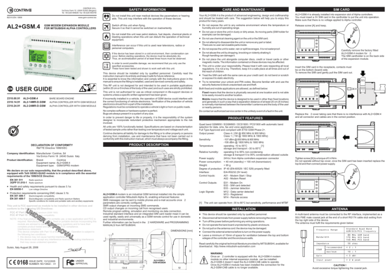
AL2+GSM.4 modem is an industrial GSM terminal installed into the simple
application controller Mitsubishi Alpha XL enabling enhanced features:
SMS messages can be sent to mobile phones and e-mail accounts once 2
parameters are correctly configured.
SMR output changes on incoming SMS commands.
CD output changes on incoming call from recognised users
Remote program editing, simulation and monitoring via data connection.
Industrial standard interface and an integrated SIM card reader mean it can be
used rapidly, easily and universally as a GSM remote control for use in domestic
and industrial environments.
Further information can be found in the 2 HARDWARE and PROGRAMMING
MANUALS from MITSUBISHI.
DIMENSIONS [mm]
Insert the SIM card in the receptacle, contacts must
be on the bottom (board) side.
To remove the SIM card gently pull the SIM card out.
¡ Try to remember your unlock and PIN codes. Become familiar with and use the
security features to block unautorised use and theft.
Mobile means that the device is designed to be used in other than fixed locations
and generally in such a way that a separation distance of at least 20 cm (8 inches)
is normally maintained between the transmitter’s antenna and the body of the user
or nearby persons.
Contrive disclaims all liability for damage to the fitting or to other property or persons
deriving from installation, use and maintenance that have not been carried out in
conformity with this instruction manual, which must always accompany the fitting.
Carefully remove the factory fitted
AL2+GSM.4 modem for 2.
The SIM cardholder is on the back side
of the expansion module.
¡ Do not abuse the unit by dropping, knocking or violenty shaking it.
Rough handling can damage it.
If incorrectly installed in a vehicle, the operation of GSM device could interfere with
the correct functioning of vehicle electronics. Verification of the protection of vehicle
electronics should form a part of the installation.
Regulations must be considered to operate a vehicle’s light or horn on public roads.
All units are 100% functionally tested. Specifications are based on characterisation
of tested sample units rather than testing over temperature and voltage each unit.
Product identification:
¡ Do not use chemical cleaning agent on the unit or the SIM card.
Fixed means that the device is physically secured at one location and is not able
to be easily moved to another location.
In order to prevent danger to life or property, it is the responsibility of the system
designer to incorporate redundant protective mechanism appropriate to the risk
involved.
R&TTE Directive 1999/5/EC
¡ Do not use or store the unit in dusty or dirty areas. Its moving parts (SIM holder for
example) can be damaged.
This unit is not authorised for use as critical component in life-support devices or
systems unless a specific written agreement has been given.
No complex software or hardware system is perfect.
Bugs are always present in a system of any size.
DECLARATION OF CONFORMITY
SIM CARD
AL2+GSM.4 is already installed into expansion slot of Alpha controllers.
You must insert a 3V SIM card in the cardholder to put the unit into operation.
Make sure that there is no voltage applied to Alpha controller.
Logic Signals:
Replace the 2 cover taking care that there is no interference with AL2+GSM.4
and all connector and cables are in the correct position.
Tighten screw [A] to a torque of 0.4 N/m.
Do not operate without top cover, once the SIM card has been inserted replace the
top lid and then connect power supply.
E01 - Modem On
E02 - SIM card detected
E03 - Jammer detection
M12 - Data carrier detected
M13 - Registered
M14 - Remote access
[1] The unit can operate from -30 to 80°C but sensitivity, performance and MTBF
INSTALLATION
¡
¡
¡
¡
¡
¡
¡
This device should be operated only by qualified personnel.
Disconnect all terminals from power supply before removing the cover.
Turn off the power before performing any wiring operations.
Do not operate the bare board unprotected by plastic enclosure.
Do not pull on the antenna cord: the device may be damaged.
Connect the external antenna before tu turn on the power supply.
Leave a minimum of 10mm of space for ventilation between the top and bottom
edeges of the controller and the enclosure walls.
Read carefully the original technical literature provided by MITSUBISHI, available for
download at: http://www.mitsubishi-automation.com
WARNING
Once an 2 controller is equipped with the AL2+GSM.4 modem
module no other internal expansion module can be installed.
AL2+GSM.4 doesn’t need the AL2-GSM-CAB cable to operate.
Once AL2+GSM.4 module has been installed the connection for the
AL2-GSM-CAB cable is no longer available.
ANTENNA
A multi-band antenna must be connected to the RF interface, implemented as a
50W FME male coaxial jack at the end of a short RG174 cable stub exiting from
the top right side of the device.
The antenna must fulfil the requirements given below:
Frequency Range
Standard Quad Band
GSM/DCS/PCS frequency
Bandwidth
80 MHz GSM band
170 MHz DCS band
140 MHZ PCS band
Impedance
VSWR
recommended
maximum
50 ohms
< 2 : 1
10 : 1
Gain
< 3 dBi
Input power
> 2 W peak
CAUTION !
Avoid excessive torque tightening the coaxial jack.
INSIDE AL2+GSM.4
Although it’s not necessary, the modem board can be removed from plastic cover.
A
B
LED indicator is located on the top right corner.
Communication socket is provided for service purposes only.
B
A
CONFIGURATION
EXAMPLE
GSM Modem parameters can be entered from the front panel keys as described
in 2 COMMUNICATION MANUAL.
Easy settings is available using the Visual Logic Software (VLS): choose Option
from the menu bar and click GSM and Serial Communication, the following dialog
box will be displayed:
COMMUNICATION CAPABILITIES
The 2 Controller has a wide range of communication capabilities that include
remote programming, sending SMS messages to telephones or Emails accounts.
Local program & control
2
OPERATING STATUS / INDICATOR
Dedicated protocol
LANDLINE
MODEM
If you want the status LED indicator is visible from outside, remove the small plastic
screen [B] shown in the figure above.
MODEM
AL2+GSM.4
Check [1] to enable the use of GSM Modem.
Select the appropriate modem type Contrive AL2+GSM.4 from the list [2]. If the
option isn't available, update the GSM.ini file located in the directory Program
Files\Alvls\BIN downloading latest version from www.gsm-control.biz.
If your SIM card is protected by PIN code insert the correct PIN in the box [3].
LED
STATUS
OFF
Modem OFF
Fast blinking
0,5s ON - 0,7s OFF
Network search
Not registered
Turning off
Slow blinking
Standby
ON
Call in progress
0,3s ON - 2,7s OFF
Registered full service
If you want to enable Remote Access through GSM connection for control and
program upload, check [4].
Leaving this option unchecked the modem can send and receive SMS and calls but
no remote data connection is allowed.
At power on a 2 sec pulse generated by ONE SHOT function will turn on the modem
activating the specific output [A01]. Instead of automatic start it’s possible to use an
input or a key to trigger the modem.
Changing default communication parameters [5] the initialization string must be
updated to new settings.
Once the GSM Modem is started the input [E01] becomes active turning on the
linked output [O06].
You may edit predefined initialization string, click Initialize Modem... [6] and the
following dialog box will open:
To avoid false indication while the GSM modem is OFF, logic signals generated by
AL2+GSM.4 will be considered only after 5 sec from regular modem start.
A special input [E03] is available to indicate the presence of a disturbing device such
as a communication JAMMER. This feature can be very important in alarm, security
and safety applications that rely on the module for communications. In these
applications, the presence of a JAMMER device can compromise the whole system
reliability and functionality and therefore shall be recognised and reported for
countermeasure actions.
An example scenario could be an intrusion detection system that uses the module for
sending the alarm indication to the system owner, and thief incomes using a Jammer
to prevent any communication through the network.
In such a case, the module detects the JAMMER presence even before the break in
and can trigger an alarm siren.
Standby
In the Standby state, the AL2+GSM.4 is registered in the network.
Paging is performed with the GSM network in order to obtain synchronisation with
the GSM network.
Power consumption in this state depends on the current network availability.
WARNING
If the GSM signal strength is less than -109dBm, AL2+GSM.4 could not
operate, verify the signal quality from Alpha controller display.
You can enter AT commands [7] that will be sent from 2 to GSM modem (only once
at 2 start-up).
A special output [A02] is provided to reset the GSM modem. This feature can be used
to recover from critical situation.
It's possible to define a delay time [8] before 2 try to make a connection to GSM
modem.
Since the modem must be turned-on within the user program, it’s suitable to set 10
seconds for modem start-up.
Using the front panel keys it's possible to verify the signal strength, the status of the
modem and errors that could occur.
INPUTS / OUTPUTS
REMOTE CONTROL
SIM PIN
The simplest way is to put your SIM card into a cellular phone and program it so it
won't ask for the PIN. The SIM card is 'open' and someone could steal the SIM card,
use it and read the information inside.
Enable PIN Code
Detailed instruction about PIN code can be found on Communication Manual
provided by MITSUBISHI.
Change default SIM PIN
It's possible to change the default PIN code provided
by your operator using any GSM mobile phone or
SIM card reader/writer.
Insert the SIM card into the SIM card holder and
follow the operating instructions provided by
phone manufacturer.
WARNING
If you insert a SIM card that asks for a PIN number different from
that stored into 2, the AL2+GSM.4 will not operate.
If you turn on 2 controller 3 times incorrectly, SIM card will lock up
and you must provide the PUK (PIN Unblocking Key).
Specific input [E02] indicates that a valid SIM card is detected.
After a predefined delay time [8] 2 try to establish a connection with the modem,
once the modem is registered in the network the Special Function Input [M13] will
turn on. The status of this special input will be updated periodically.
Network search
In the network search state the AL2+GSM.4 searches for a GSM network in order to
register to main operator or to the roaming service provider.
The network search takes few seconds until AL2+GSM.4 is registered.
If the LED indicator continues to flash rapidly, this means that no SIM card is inserted,
an incorrect PIN number was provided or the antenna is missing.
Call in progress
When an incoming call is detected or issuing a call, a connection on the network is
established. If 2 is configured for REMOTE ACCESS AL2+GSM.4 will respond to
incoming calls, establishing a data link.
GSM
MODEM
In the above simple Visual Logic Software (VLS) program example the controls
available for GSM Modem AL2+GSM.4 are shown.
Some specific inputs and outputs are used to control the AL2+GSM.4 modem :
SIGNAL
I/O
DESCRIPTION
A01
OUTPUT
Turn ON/OFF GSM modem (pulse > 1s)
A02
OUTPUT
Reset GSM modem
E01
INPUT
Modem running
E02
INPUT
Valid SIM card found
E03
INPUT
Jammer detected
M12
INPUT
Data carrier detected
M13
INPUT
GSM network registration
M14
INPUT
Remote access
CAUTION
To use both Remote Access [4] and Call Detect at same time, define the
number of rings ' x ' in ATS0=x longer than Number of RING before call
detect otherwise the controller try to establish a data connection with
calling party before to serve the incoming control call.
Refer to COMMUNICATION MANUAL for details.
In the example above output 1 [O01] is controlled using two special features:
When an incoming call is detected the output will be activated.
It’s possible to leave this control option open to anyone or specify
the authorised telephone number (Caller Line Identification
Presentation must be enabled on the caller phone).
The output is activated or deactivated following the remote control
command defined and received like SMS.
It’s possible to leave this control option open to anyone or specify
the authorised telephone number (Caller Line Identification
Presentation must be enabled on the caller phone).
In the example above a message will be issued when input 4 [I04] is closing.
The text shown on the display will be sent to specified destination
like SMS or Email, depending on specific configuration.
PERSONAL
COMPUTER
+
AL2-VLS/WIN-E
SMS / EMAIL &
REMOTE ACCESS
PERSONAL
COMPUTER
+
AL2-VLS/WIN-E
or
SPECIFIC
APPLICATION
TELEPHONE SUPPORTING
SMS / EMAIL MESSAGES
The 2 Controller can be used to monitor and control machines in remote stations
and notify maintenance personnel in case of machine error or emergency situations.
Remote monitoring through the AL-VLS/WIN-E software (version 2.00 onwards) can
provide machine production and status updates as well as enable programming or
parameter updates without the necessity of local access.
While the AL2+GSM.4 is installed into 2 or an external device is linked through AL232-GSM cable [10], it will be possible to use left side com port to communicate with
local Personal Computer through specific cable [9] AL2-232-CAB.
SMS delivery failure is usually less than 1% but you must keep in mind
that a message could not arrive and you cannot complain with your
operator for this.
This product is subject to Directive 2002/96/EC of the European
Parliament and the Council of the European Union on waste electrical
and electronic equipment (WEEE) and, in jurisdictions adopting that
Directive, is marked as being put on the market after August 13, 2005,
and should not be disposed of as unsorted municipal waste.
Please utilize your local WEEE collection facilities in the disposition of
this product and otherwise observe all applicable requirements.
CONTRIVE RESERVES THE RIGHT TO MODIFY THE CHARACTERISTICS STATED
IN THIS INSTRUCTION MANUAL AT ANY TIME AND WITHOUT PRIOR NOTICE.
© COPYRIGHT 2002...2005 CONTRIVE SRL ITALY. ALL RIGHTS RESERVED.
THE INFORMATION CONTAINED IN THIS DOCUMENT ARE SUBJECT TO CHANGE
WITHOUT NOTICE. PRODUCT NAMES, CORPORATE NAMES OR TITLES USED WITHIN
THIS DOCUMENT MAY BE TRADEMARKS OR REGISTERED TRADEMARKS OF OTHER
COMPANIES AND ARE MENTIONED ONLY IN AN EXPLANATORY MANNER TO THE
READERS’ BENEFIT, AND WITHOUT INTENTION TO INFRINGE.
WHILE EVERY EFFORT HAS BEEN MADE TO MAKE SURE THE INFORMATION IN THIS
DOCUMENT IS CORRECT, CONTRIVE CAN NOT BE LIABLE FOR ANY DAMAGES
WHATSOEVER FOR LOSS RELATING TO THIS DOCUMENT.
WARRANTIES
CONTRIVE GUARANTEES FOR TWO YEARS FROM THE DATE OF MANUFACTURE OF
ITS PRODUCT TO REPLACE, OR, AT ITS OPTION, TO REPAIR ANY PRODUCT OR PART
THEREOF WHICH IS FOUND DEFECTIVE IN MATERIAL OR WORKMANSHIP OR WHICH
OTHERWISE FAILS TO CONFORM TO THE DESCRIPTION OF ITS SALES ORDER.
CONTRIVE MAKES NO WARRANTY OF MERCHANTABILITY OR ANY OTHER
WARRANTY EXPRESS OR IMPLIED. IN NO EVENT SHALL CONTRIVE BE LIABLE FOR
CONSEQUENTIAL OR SPECIAL DAMAGES OF ANY NATURE WHICH MAY ARISE IN
CONNECTION WITH SUCH PRODUCTS.
THE WARRANTY DOES NOT APPLY IN CASE OF IMPROPER USE
Alpha XL
SIMPLE APPLICATION CONTROLLERS ARE MANUFACTURED BY
Refer to COMMUNICATION MANUAL for details.
MITSUBISHI


