(chapter 24) microwave radio communications and system gain
advertisement
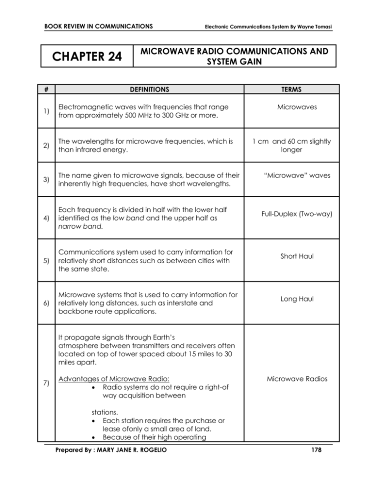
BOOK REVIEW IN COMMUNICATIONS CHAPTER 24 # Electronic Communications System By Wayne Tomasi MICROWAVE RADIO COMMUNICATIONS AND SYSTEM GAIN DEFINITIONS 1) Electromagnetic waves with frequencies that range from approximately 500 MHz to 300 GHz or more. 2) The wavelengths for microwave frequencies, which is than infrared energy. 3) The name given to microwave signals, because of their inherently high frequencies, have short wavelengths. 4) Each frequency is divided in half with the lower half identified as the low band and the upper half as narrow band. 5) Communications system used to carry information for relatively short distances such as between cities with the same state. 6) Microwave systems that is used to carry information for relatively long distances, such as interstate and backbone route applications. TERMS Microwaves 1 cm and 60 cm slightly longer “Microwave” waves Full-Duplex (Two-way) Short Haul Long Haul It propagate signals through Earth’s atmosphere between transmitters and receivers often located on top of tower spaced about 15 miles to 30 miles apart. 7) Advantages of Microwave Radio: Radio systems do not require a right-of way acquisition between Microwave Radios stations. Each station requires the purchase or lease ofonly a small area of land. Because of their high operating Prepared By : MARY JANE R. ROGELIO 178 BOOK REVIEW IN COMMUNICATIONS Electronic Communications System By Wayne Tomasi frequencies, microwave radio systems can carry large quantities of information. High frequencies mean short wavelengths, which require relatively small antennas. Radio signals are more easily propagated around physical obstacles such as water and high mountains Fewer repeaters are necessary for amplification. Distances between switching centers are less. Underground facilities are minimized. Minimum delays are introduced. Minimal crosstalk exists between voice channels. Increased reliability and less maintenance are important factors. Disadvantages of Microwave Radio: It is more difficult to analyze and design circuits at microwave frequencies. Measuring techniques are more difficult to perfect and implement at microwave frequencies. It is difficult to implement conventional circuit components at microwave frequencies. Transient time is more critical at microwave frequencies. It is often necessary to use specialized components for microwave frequencies. Microwave frequencies propagate in a straight line, which limits their use to lineof-sight applications. 8) 9) Propagates signals outside the Earth’s atmosphere and are capable of carrying signals much farther while utilizing fewer transmitters and receivers. It is used in microwave radio systems rather than amplitude modulation because AM signals are more sensitive to amplitude nonlinearities inherent in wideband microwave amplifiers. Prepared By : MARY JANE R. ROGELIO Satellite Systems Frequency Modulation 179 BOOK REVIEW IN COMMUNICATIONS 10) Electronic Communications System By Wayne Tomasi Major factor when designing FM Radio systems. It is caused by repeater amplitude nonlinearity in AM, while in FM, it is caused by transmission gain and delay distortion. Intermodulation Noise The composite signal that modulates the FM carrier and may comprise one or more of the following: 11) 12) Frequency-division multiplexed voiceband channels Time-division-multiplexed voice-band channels Broadcast-quality composite video or picture phone Wideband data It provides an artificial boost in amplitude to the higher baseband frequencies. 13) Frequency modulation index used in the FM deviator. Typically, modulation indices are kept between 0.5 and 1. 14) FM signal that is produces at the output of the deviator with a low-index frequency modulation. 15) A receiver and a transmitter placed back to back or in tandem with the system. 16) It receives a signal, amplifies and reshapes it, and then retransmit the signal to the next repeater or terminal station down line from it. Types of Microwave repeaters: IF Baseband RF Prepared By : MARY JANE R. ROGELIO Baseband Preemphasis Network Low-Index Narrowband FM Microwave Repeaters Repeater Station 180 BOOK REVIEW IN COMMUNICATIONS Electronic Communications System By Wayne Tomasi 17) The received RF carrier is down-converted to an IF frequency, amplified, reshaped, up-converted to an RF frequency, and then retransmitted. 18) Generally less than 9 MHz. 19) The range id 60 MHz to 80MHz. 20) Another name for a Local oscillator, is considerably lower in frequency than either the received or the IF Repeater Baseband Frequencies IF frequencies Shift Oscillator transmitted radio frequencies. 21) Transmission used by microwave systems wherein a direct signal path must exist between the transmit receive antennas. 22) A temporary reduction in signal strength which last in milliseconds for several hours or even days. 23) It suggests that there is more than one transmission path or method of transmission available a transmitter and a receiver. 24) It is simply modulating two different RF carrier frequencies with the same IF intelligence, then transmitting both RF signals to a given destination. 25) The output of a transmitter is fed to two or more antennas that are physically separated by an appreciable number of wavelengths. 26) A single RF carrier is propagated with two different electromagnetic polarizations. It is generally used in conjunction with space diversity. Prepared By : MARY JANE R. ROGELIO Line-of Site Transmission Radio Fade Diversity Frequency Diversity Space Diversity Polarization Diversity 181 BOOK REVIEW IN COMMUNICATIONS Electronic Communications System By Wayne Tomasi 27) It is more than one receiver for a single radio-frequency channel. With frequency diversity, it is necessary to also use receiver diversity because each transmitted frequency requires its own receiver 28) Another form of Hybrid diversity and undoubtly provides the most reliable transmission but most expensive. It combines frequency, space, polarization and receiver diversity into one system. 29) A specialized form of diversity that consist of a standard frequency diversity path where the two transmitter/ receiver pairs at one end of the path are separated from each other and connected to different antennas that are vertically separated as in space diversity. Alternate facilities temporarily made to avoid a service interruption during periods of deep fades or equipment failures. 29) types of protection switching arrangements: hotstandby diversity 30) Each working radio channel has a dedicated backup or spare channel. 31) A single backup channel is made available to as many as 11 working channels. 32) In hotstandby protection, it splits the signal power and directs it to the working and the spare (standby) microwave channels simultaneously. 33) It has two working channels, one spare channel, and an auxiliary channel. Prepared By : MARY JANE R. ROGELIO Receiver Diversity Quad Diversity Hybrid Diversity Protection Switching Arrangement Hot Standby Protection Diversity Protection Head-End Bridge Diversity Protection 182 BOOK REVIEW IN COMMUNICATIONS Electronic Communications System By Wayne Tomasi 34) A low-capacity low-power microwave radio that is designed to be used for a maintenance channel only. 35) It is where the number of repeater stations between protection switches depends. 36) Points in the system where baseband signals either originate or terminate. four major sections: baseband wireline entrance link (WLEL) FM-IF RF sections 37) Points in a system where baseband signals may be reconfigured or where RF carriers are simply “repeated” or amplified. 38) Stands for WireLine Entrance Link, it serves as the interface between the multiplex terminal equipment and the FM_IF equipment. 39) A balanced modulator that, when used in conjunction with a microwave generator, power amplifier, and band-pass filter, up-converts the IF carrier to an RF carrier and amplifies the RF to the desired output power. Auxilliary Channel Reliability Objectives of the Systems Terminal Stations Repeater Stations WLEL Transmod It must be capable of amplifying very high frequencies and passing very wide bandwidth signals for microwave radios. 40) devices used in microwaveamplifiers: Klystron Tubes Traveling-wave tubes (TWTs) IMPATT (Impact avalanche and transit time) Prepared By : MARY JANE R. ROGELIO Power Amplifiers 183 BOOK REVIEW IN COMMUNICATIONS Electronic Communications System By Wayne Tomasi 41) It provides the RF carrier input to the up-converter. It is called as microwave generator rather than an oscillator because it is difficult to construct a stable circuit that will oscillate in the gigahertz range. 42) It operates in the range 5 MHz to 25 MHz, used to provide a base frequency that is multiplied up to the desired RF carrier frequency. 43) A unidirectional device often made from ferrite material. It used in conjunction with a channelcombining network to prevent the output of one transmitter from interfering with the output of another transmitter. 44) Stands for Automatic Gain Control, is a circuit in an IF amplifier. 45) It occurs only when three stations are placed in a geographical straight line in the system. 46) It prevents the power that “leaks” out the back and sides of a transmit antenna from interfering with the signal entering the input of a nearby receive antenna. 47) The signal entering the input of a nearby receive antenna. Ring around 48) It means that this channels are propagated with vertical polarization. V Channels 49) The line-of-sight directly between the transmit and receive antenna. Also called as the Direct Wave. 50) It consists of the electric and magnetic fields associated with the currents induced in earth’s surface. Prepared By : MARY JANE R. ROGELIO Microwave Generator Crystal-controlled Oscillator Isolator AGC Multi-hop Interference High/Low-Frequency Scheme Free-Space Path Surface Wave 184 BOOK REVIEW IN COMMUNICATIONS Electronic Communications System By Wayne Tomasi 51) The portion of the transmit signal that is reflected off Earth’s surface and captured by the receive antenna. 52) The portion of the transmit signal that is returned back to Earth’s surface by the ionized layers of earth’s atmosphere. 53) The loss incurred by an electromagnetic wave as it propagates in a straight line through a vacuum with no absorption or reflection of energy from nearby objects. 54) A phenomenon wherein electromagnetic energy is spread out as it propagates away from the source resulting in lower relative power densities. The reduction in signal strength at the 55) Ground-Reflected Wave Sky Wave Free-Space Path Loss Spreading Loss Fading input to a receiver. 56) 57) 58) The difference between the nominal output power of a transmitter and the minimum input power to a receiver necessary to achieve satisfactory performance. Sometimes called as Link Margin, is essentially a “fudge Factor” included in system gain equations that considers the non ideal and less predictable characteristics of radio wave propagation and terrain sensitivity. He described ways of calculating outage time due to fading on a non diversity path as a function of terrain, climate, path length, and fade margin, in April 1969. Prepared By : MARY JANE R. ROGELIO System Gain Fade Margin W.T. Barnett 185 BOOK REVIEW IN COMMUNICATIONS Electronic Communications System By Wayne Tomasi 59) From Bell Laboratories, he derived formulas for calculating the effective improvement achievable by vertical space diversity as a function of the spacing distance, path length, and frequency in June 1970. 60) The ratio of the wideband “carrier” to the wideband noise power. 61) Also called Receiver Sensitivity, is the minimum wide band carrier power at the input to a receiver that will provide a usable baseband output. 62) 63) The carrier-to-noise ratio before the FM demodulator. The carrier-to-noise ratio after the FM demodulator. Arvids Vignant Carrier-to-Noise Ratio (C/N) Receiver Threshold Pre-detection Signal toNoise Ratio Postdetection Signalto-Noise Ratio 64) A ratio of input signal-to-noise ratio to output signal to noise ratio. Noise Factor (F) 65) The noise factor stated in dB and is a parameter commonly used to indicate the quality of a receiver. Noise Figure Prepared By : MARY JANE R. ROGELIO 186
