Mega-Guard Series - terasaki electric co.
advertisement

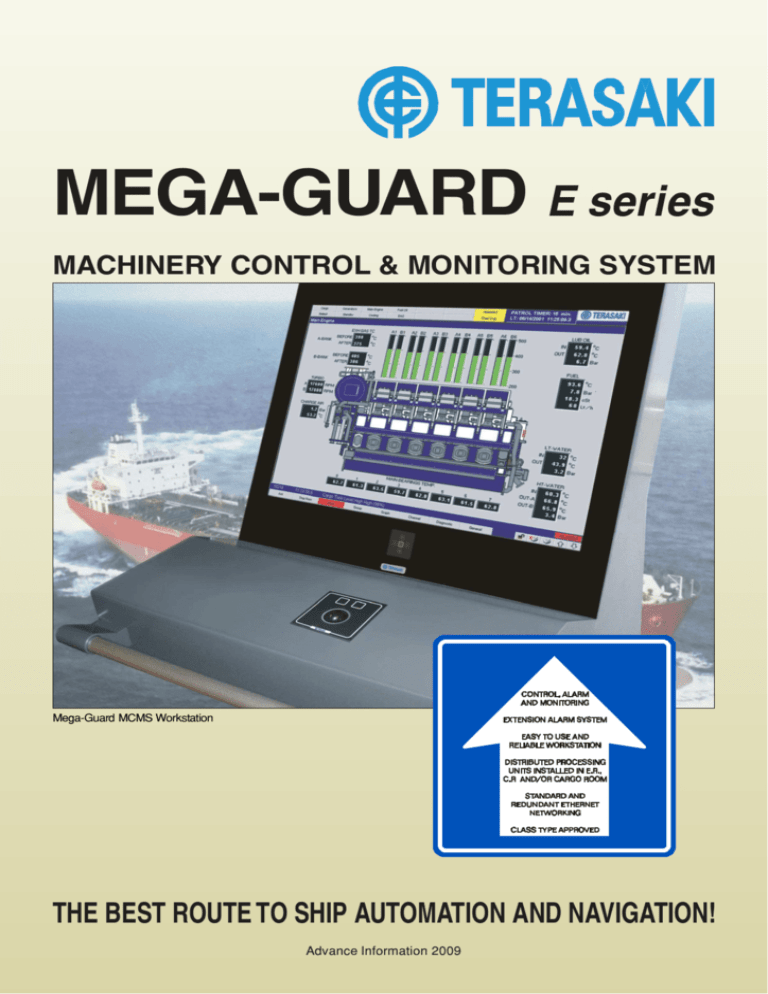
MEGA-GUARD E series MACHINERY CONTROL & MONITORING SYSTEM Mega-Guard MCMS Workstation THE BEST ROUTE TO SHIP AUTOMATION AND NAVIGATION! Advance Information 2009 MCMS Features Functions: The Mega-Guard Machinery Monitoring and Control System is the perfect automation solution for medium to large size vessels. It can be used as a stand-alone Machinery Control and Monitoring System or the Mega-Guard can be extended with Power Management, Cargo Control, Propulsion Control, Integrated Navigation and Dynamic Positioning functions. The Mega-Guard Ship Automation System is the most reliable and field proven automation system as can be found on the market because of the following facts: Operator Workstations built-up with Marine Personal Computers under Windows XP embedded operating system and redundant Ethernet link. Solid state disk is applied instead of hard disk. Main and Back-up Workstation to further ensure safety and reliability Distributed Processing Units built-up with Control Processors equipped with I/O Module and redundant Ethernet link. Each I/O Modules has its own isolated sensor supply and earth fault detector. Extension Alarm System is built-up with EAS Operator Panels equipped with a graphic LCD display and 12 illuminated pushbuttons with redundant Ethernet link. Operator Workstation with Color Graphic Screen and user-friendly Operator Keyboard with Trackball Whole system inter-connected by redundant Ethernet link. Cabling with Star topology or Ring topology or a combination of Star and Ring topology. Whole system operating directly on 19-32VDC power supply and all components have low power consumption. Uninterruptable Power Supply providing fail safe 24VDC output. Programming in accordance with international PLC programming standard IEC61131-3 (ST). Type approved by all major class classification societies. Operator Workstations: An Operator Workstation consists out of a TFT colour graphic screen, Operator Keyboard with Trackball, Marine Personal Computer and optional Printer. The Operator Workstation provides a reliable and user-friendly operator interface to ensure safe operation. The Operator Workstations are connected to each other via the redundant Ethernet link based upon UTP cabling. Two Operator Workstations, called the Main Server and the Back-up Server, are communicating via the redundant Ethernet link with the Control Processor with I/O Modules (Distributed Processing Units) and to the Extension Alarm System. This ensures a full redundant lay-out. Client Operator Workstations communicate with either the Main Server or Back-up Server Operator Workstation via the redundant Ethernet link. The On Duty Selection and Engineer Calling functions are fully redundant as upon failure of an Operator Workstation, the extension alarm system functions are automatically transferred to a back-up Operator Workstation. -2- Advance Information 2009 I/O Modules & Extension Alarm Distributed Processing Units: L.O. AUTO FILTER DI FF. PRESSURE 2 EM ERG. FIRE PUM P ABNORMAL 3 M/E SAFETY AIR NOT VENTED M/E CYL. LUBRICATORA NON FL OW M/E CYL. LUBRICAT ORB LEVEL LOW 4 CASCADE & INSPEC TANK LEVEL M/E CYL. LUBRICAT ORB NON FL OW 5 SLUDGE TANK HIGH LEVEL B A B A Control Processors with I/O Modules (also called DPU) are mounted on a DIN rail; close to sensors and actuators to minimize cabling. The Control Processor is connected to the redundant Ethernet link for communication with the Main and Back-up Server Operator Workstations and for communication with other Control Processors. Each I/O channel on an I/O Module has a LED indication and a channel identification text window. This can be used for back-up and local read-out of alarms and status. Each I/O Module is equipped with an isolated sensor supply in order to feed sensors. In addition, the I/O Module contains an earth fault detector. A Control Processor with I/O Modules fully executes control, alarm and monitoring functions even when no Operator Workstation is connected. Programming of control functions is done via the programming language PAL1131 which is in accordance with international PLC standard IEC61131-3 (ST). Sensors and actuators are directly wired to the detachable terminal strips on the I/O Modules. B A B A B A 6 B A 7 B A 8 B B A 11 B A 12 B A 15 B A 16 B A 17 B A 18 B B1 C A B2 A B3 C B A B A 23 B B.W. BENEATH M/E M/E OIL MIST DETECT FAIL 27 PART No. X103 F. O. DRAINTANK HIGH LEVEL M/E SCAV.AIR W. MIST CATCHER HIGH LEVEL A 24 B A B A B A B A 28 B M /E LO CIRC. TANK LOW LEVEL M/E No .1 PISTONCOOL OIL OUTL ET F LOW M/E No .2 PISTONCOOL OIL OUTL ET F LOW STERNL O DRAINTANK HIGH LEVEL M/E No .3 PISTONCOOL OIL OUTL ET F LOW STERNL O FORE SEAL TANK LOW LEVEL STERNL O AFT SEAL ANK HIGH LEVEL M/E No .4 PISTONCOOL OIL OUTL ET F LOW M/E No .5 PISTONCOOL OIL OUTL ET F LOW STERNL O AFT SEAL ANK LOW LEVEL M/E No .6 PISTONCOOL OIL OUTL ET F LOW 34 PIPE TUNNEL BILGE HIGH LEVEL M/E AXIAL VIBRATI ON 35 COF FERDAM BIL GE HIGH LEVEL M/E AXIAL VABRATION POWER FAIL URE 36 No. 1ALTERNATOR WINDING U TEMPERATURE No. 2ALTERNATOR WINDING U TEMPERATURE 13 B No. 1ALTERNATOR WINDING V TEM PERATURE No. 2ALTERNATOR WINDING V TEM PERATURE 14 B No. 1ALTERNATOR WINDING W T EMPERATURE No. 2ALTERNATOR WINDING W T EMPERATURE 15B No . 1 G/E L OI NPRESSURE No . 2 G/E L OI NPRESSURE 16 B No . 1 G/E LO INT EMPERAT URE No . 2 G/E LO INT EMPERAT URE 17 B No . 1 G/E H.T.F.W. OUTLET TEMPERATURE No . 2 G/E H.T.F.W. OUTLET TEMPERATURE 18 B PART No. X102 No . 1 G/E F.O. INL ET PRESSURE No . 2 G/E F.O. INL ET PRESSURE WASTE OIL TANK HIGH LEVEL B 14 A 26 13 B B 22 M/E OIL MIST DENSITY CRANKCASE A A A 21 25 B 10 B 20 M/E SAFETY AIR INLET PRESSURE 9 A M/E F.O. LEAKAGE HIGH LEVEL M/E EXH. V/V SPRINGAIR PRESSURE A 19 EMERG. FIRE PUMP ROOM BIL GE HIGHL EVEL OILY BILGE W. SEPARATOR OILY CONTENT HIGH OILY W. SEPARATOR OILY CONTENT HIGH A C The Machinery Monitoring and Control System executes the following functions: M/E CYL. LUBRICATORA LEVEL LOW 1 A A 29 B A 30 B A 31 B A 32 B A 33 B A B A B A B C A C A C A B4 A C Alarm and monitoring Exhaust gas monitoring Tank gauging Master / Stand-by pump control Motor / Pump starter Compressor control , Master / follower Valve Control and monitoring Temperature Control (PID) etc. C A B5 A C A B6 C C A B7 C A C A 19 B C A A B8 20 B C A The following I/O Modules are available: B9 C A B10 24 channel Mixed I/O Module with 4 Analog Outputs and 20 configurable Inputs and/or Outputs (AI, AO, DI, DO, PI) 31 channel PMS I/O Module 36 channel Digital Input I/O Module 18 channel Digital Input and 18 Relay Output I/O Module 24 channel Analog Input I/O Module C C A No . 1 H. F.O. SERVICE TANK TEMPERATURE No . 1 H. F.O. TANK (P) TEMPERATURE 21 B No . 2 H. F.O. SERVICE TANK TEMPERATURE No . 1 H. F.O. TANK (S) TEMPERATURE 22 B No . 1 H. F.O. SETT L. TANK TEMPERATURE No . 2 H. F.O. TANK (P) TEMPERATURE 23 B No . 2 H. F.O. SETT L. TANK TEMPERATURE No . 2 H. F.O. TANK (S) TEMPERATURE 24 B SYSTEM ON SYSTEM FAIL URE C A C A B11 C A B12 C A C A C Par t No.: 98 .6.049.706 CON TR OL PROC ESSOR BO ARD ID: XP101 A Control Processor supports up to 8 I/O Modules and supports up to 4 Serial links to external devices. Serial interface links will be connected via the Modbus RTU or NMEA protocol (other protocols optional). The Control Processors and I/O Modules and Serial link interfaces are installed in DPU Cabinets or inside a console on a DPU DIN rail. 1 24Vdc 2 0Vdc 3 FAIL C 4 FAIL NC 5 HORN C 6 HORN NO E THERNET MAIN E THERNET BACKUP ETH M ETH BU C ontrol Processor with 2 I/O Module s Extension Alarm System The Extension Alarm System is a highly reliable engineer calling system, which extends the Mega-Guard Ship Automation System for unmanned machinery space operation. On Duty Selection and Engineer Calling functions are executed on a dedicated mimic on the Operator Workstation. The dedicated mimic display on the Operator Workstation contains the following fields: CALL ECR GROUP 1 MAIN ENGINE GROUP 2 GENERATOR ENGIN E GROUP 3 AUX. MACHINERY GROUP 4 SAFETY SYSTEM ON DUTY CALL BRIDGE GROUP 5 TANK & BILGE GROUP 6 ELECTRIC GROUP 7 STEERING GEAR GROUP 8 NON VITAL FIRE ALARM On duty selection Attended / unattended (manned / unmanned) engine room Engineer calling, Patrol timer / engineer safety system (dead man timer) EAS Operator Panels are installed in Bridge and Accommodation areas. The EAS Operator Panels are equipped with the following: FAULT SYSTEM ON 8 line / 40 character display displaying individual alarms On Duty lamp 8x Group Alarm lamp & buzzer EAS Operato r Panel -3- Advance Information 2009 Fire Alarm lamp with buzzer Call ECR / Call Bridge pushbutton / lamp Accept / Stop Horn pushbutton Dimming pushbuttons (Arrow Left / Right)


