Novel Design Method of Dual–Band Antenna for WLAN Applications
advertisement

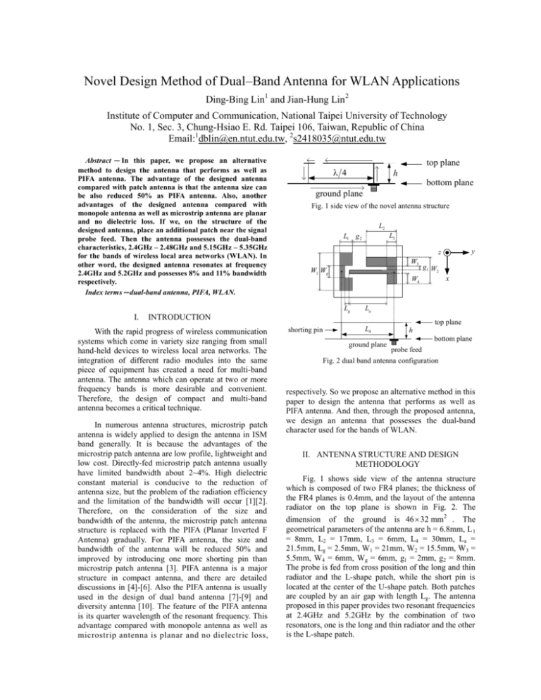
Novel Design Method of Dual–Band Antenna for WLAN Applications Ding-Bing Lin1 and Jian-Hung Lin2 Institute of Computer and Communication, National Taipei University of Technology No. 1, Sec. 3, Chung-Hsiao E. Rd. Taipei 106, Taiwan, Republic of China Email:1dblin@en.ntut.edu.tw, 2s2418035@ntut.edu.tw Abstract - In this paper, we propose an alternative method to design the antenna that performs as well as PIFA antenna. The advantage of the designed antenna compared with patch antenna is that the antenna size can be also reduced 50% as PIFA antenna. Also, another advantages of the designed antenna compared with monopole antenna as well as microstrip antenna are planar and no dielectric loss. If we, on the structure of the designed antenna, place an additional patch near the signal probe feed. Then the antenna possesses the dual-band characteristics, 2.4GHz – 2.48GHz and 5.15GHz – 5.35GHz for the bands of wireless local area networks (WLAN). In other word, the designed antenna resonates at frequency 2.4GHz and 5.2GHz and possesses 8% and 11% bandwidth respectively. Index terms-dual-band antenna, PIFA, WLAN. top plane λ 4 h bottom plane ground plane Fig. 1 side view of the novel antenna structure L2 W1 Wg In numerous antenna structures, microstrip patch antenna is widely applied to design the antenna in ISM band generally. It is because the advantages of the microstrip patch antenna are low profile, lightweight and low cost. Directly-fed microstrip patch antenna usually have limited bandwidth about 2~4%. High dielectric constant material is conducive to the reduction of antenna size, but the problem of the radiation efficiency and the limitation of the bandwidth will occur [1][2]. Therefore, on the consideration of the size and bandwidth of the antenna, the microstrip patch antenna structure is replaced with the PIFA (Planar Inverted F Antenna) gradually. For PIFA antenna, the size and bandwidth of the antenna will be reduced 50% and improved by introducing one more shorting pin than microstrip patch antenna [3]. PIFA antenna is a major structure in compact antenna, and there are detailed discussions in [4]-[6]. Also the PIFA antenna is usually used in the design of dual band antenna [7]-[9] and diversity antenna [10]. The feature of the PIFA antenna is its quarter wavelength of the resonant frequency. This advantage compared with monopole antenna as well as microstrip antenna is planar and no dielectric loss, g1 W2 x W4 La INTRODUCTION With the rapid progress of wireless communication systems which come in variety size ranging from small hand-held devices to wireless local area networks. The integration of different radio modules into the same piece of equipment has created a need for multi-band antenna. The antenna which can operate at two or more frequency bands is more desirable and convenient. Therefore, the design of compact and multi-band antenna becomes a critical technique. y z W3 Lg I. L3 L1 g 2 top plane shorting pin L4 ground plane h bottom plane probe feed Fig. 2 dual band antenna configuration respectively. So we propose an alternative method in this paper to design the antenna that performs as well as PIFA antenna. And then, through the proposed antenna, we design an antenna that possesses the dual-band character used for the bands of WLAN. II. ANTENNA STRUCTURE AND DESIGN METHODOLOGY Fig. 1 shows side view of the antenna structure which is composed of two FR4 planes; the thickness of the FR4 planes is 0.4mm, and the layout of the antenna radiator on the top plane is shown in Fig. 2. The dimension of the ground is 46 × 32 mm2 . The geometrical parameters of the antenna are h = 6.8mm, L 1 = 8mm, L2 = 17mm, L3 = 6mm, L4 = 30mm, La = 21.5mm, Lg = 2.5mm, W1 = 21mm, W2 = 15.5mm, W3 = 5.5mm, W4 = 6mm, Wg = 6mm, g1 = 2mm, g2 = 8mm. The probe is fed from cross position of the long and thin radiator and the L-shape patch, while the short pin is located at the center of the U-shape patch. Both patches are coupled by an air gap with length Lg. The antenna proposed in this paper provides two resonant frequencies at 2.4GHz and 5.2GHz by the combination of two resonators, one is the long and thin radiator and the other is the L-shape patch. (a) (b) Fig. 3 Current distribution at frequency (a) 2.4GHz (b) 5.2GHz. The lower resonant frequency is determined by the length of long and thin radiator and the length of air gap. We set L 4 = λ 4 of the lower resonant frequency 2.4GHz, then tuning the appropriate length of air gap and the appropriate dimensions of the U-shape patch for a good impedance match on the lower resonant frequency. For the fixed length L4, increasing the length of air gap is equivalent to reducing the length of the long and thin radiator. The simulation result of the current distribution for the frequency 2.4 GHz is shown in Fig. 3-(a). In which, the current distribution on the long and thin radiator shows the same direction. Both the current distributions on the U-shape patch and the L-shape patch show the opposite direction and flow into the node of short pin or probe feed. Hence the dominant radiation effect comes from the current distribution on the long and thin radiator. The higher resonant frequency is dominated by the dimension of L-shape patch. In our design, we set L2 + W2 = λ 2 of the higher resonant frequency 5.2GHz. Also, the air gap Lg and the U-shape patch are needed to provide a good impedance on both resonant frequencies. Observe the simulation results, shown in Fig. 3-(b), of the current distribution for the higher resonant frequency 5.2GHz. Both the current distribution on long and thin radiator and L-shape patch show the same direction, while the current distribution of the U-shape patch shows the opposite direction and flows into the node of the short pin. The dominant radiation effect comes from the current distribution on both the L-shape patch and the long and thin radiator. Hence, not only the dimension of the L-shape patch will affect the higher resonant frequency but also the length of the long and thin radiator. Through the above descriptions, the design procedure can be summarized as the following: 1. To decide the length of L4 such that the antenna resonates at the lower resonant frequency. 2. Tuning the dimensions W1, Wg and L of U-shape patch and set a sufficient long air gap to get good impedance on the lower resonant frequency. 3. Place an additional L-shape patch near the signal probe feed and decide the length of L2+W2 such that the antenna can also resonate at the higher resonant frequency. 4. Tuning the length of long and thin radiator for fine tuning the higher resonant frequency. III. SIMUALTION AND MEASUREMENT RESULTS The characteristics of the radiation can be confirmed through the simulation software Ansoft Ensemble using the analysis of moment method and the automatic measurement system set up on an anechoic chamber. Fig. 4 shows the simulation results of the resistance and reactance of the dual-band antenna. Figure 5 shows the simulation and measurement results of return loss. The measurement results are good agreement with the simulation results. And the designed antenna resonates at frequencies 2.4GHz and 5.2GHz, and the bandwidths are 200MHz and 600MHz respectively. Figures 6 and 7 are the return loss for different L2 and different Lg respectively. The shorter L2 increases the higher resonant frequency from 5.08 GHz to 5.4 GHz. In addition, the longer air gap Lg, equivalent to the shorter La for a fixed length L4, increases the higher resonant frequency from 5.08 GHz to 5.34 GHz. But, varying L2 and Lg has not impact on the lower resonant frequency. Although the length Lg of air gap will effect the impedance matching condition, that is more insensitive than the dimension of U-shape patch. It is found that the resonance frequencies can be adjusted independently, which makes the design procedure simpler. Fig. 4. The impedance of the designed antenna Fig. 6. The influence of the resonant frequency for different L2 Fig. 5. Return loss of the simulation and measurement results Fig. 7. The influence of the resonant frequency for different Lg The measured radiation patterns are shown in Figs. 8-11. The antenna gains are 3.46dBi and 7dBi at frequencies 2.4GHz and 5.2GHz, respectively. The simpler design procedure has been pointed out in the previous section. and upper resonant frequencies as 8% and 11% respectively. The experimental results obtained show good radiation characteristics for two operating bands of a WLAN antenna. REFERENCE IV. CONCLUSION The novel design method of dual-band antenna is introduced in this paper for wireless local area networks applications at 2.4GHz and 5.2GHz bands. It can be utilized to perform the multi-band or dual-band antenna due to easy combination with other type antennas. Moreover, both the two resonant frequencies can be adjusted independently through the variations of the parameters of the antenna dimension. The characteristics of the radiation can be confirmed through the simulation software Ansoft Ensemble and the automatic measurement system. Therefore, the two resonant frequencies can be designed individually which makes the design procedure simpler. The bandwidths of the designed dual-band antenna were found for the lower [1] Zhan Li, Yahya Rahmat-Samii, Teemu Kaiponenz, “Bandwidth study of a dual band PIFA on a fixed substrate for wireless communication,” IEEE 2003 Transactions on Antennas and Propagation, Vol 1, pp 435-438, June 2003. [2] C. A. Balanis, Antenna theory: analysis and design, chapter 14, John Wiley & Sons, 1997. [3] R. Chair, K.M. Luk and K.F. Lee., “Simulation of Bandwidth Enhancement on the Quarter-Wave Shorted Patch By Adding a Shorting Pin,” IEEE 2001 International Symposium of Antennas and Propagation Society, Vol 1, pp 82-85, July 2001. [4] Rowell C.R., Murch R.D., “A capacitively loaded PIFA for compact mobile telephone handsets,” IEEE Transactions on Antennas and Propagation, Vol 45, pp 837-842, May 1997. [5] Virga K.L. Rahmat-Samii Y., “Low-profile enhanced-bandwidth PIFA antennas for wireless communications packaging,” IEEE Transactions on Microwave Theory and Techniques, Vol 45, pp 1879-1888, Oct. 1997. [9] [6] Panayi P.K., Al-Nuaimi M.O., and Ivrissimtzis I.P., “Tuning techniques for planar inverted-F antenna,” Electronics Letters, Vol 37, pp 1003-1004, Aug. 2001. [10] Kin-Lu Wong, An-Chia Chen, Yen-Liang Kuo, [7] Karmakar N.C., “Shorting strap tunable single feed dual-band stacked patch PIFA,” Antennas and Wireless Propagation Letters, Vol 2, pp 68-71, 2003. [8] Karmakar N.C., “Shorting strap tunable dual-band stacked PIFA,” IEEE 2003 International Symposium of Antennas and Propagation Society, Vol 3, pp 74-77, June, 2003. Fig. 8. xz-plane at 2.4GHz Fu-Ren Hsiao, Wen-Shyang Chen, Kin-Lu Wong, “Dual-frequency PIFA with a rolled radiating arm for GSM/DCS operation,” IEEE 2003 International Symposium of Antennas and Propagation Society, Vol 3, pp 103-106,June, 2003. “Diversity metal-plate planar inverted-F antenna for WLAN operation,” Electronics Letters, Vol 39, pp 590-591, April 2003 Fig. 9. yz-plane at 2.4GHz . Fig. 10. xz-plane at 5.2GHz Fig. 11. yz-plane at 5.2GHz


