SAGE Terminal
advertisement
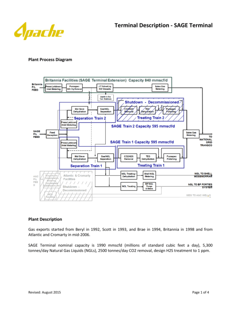
Terminal Description - SAGE Terminal Plant Process Diagram Plant Description Gas exports started from Beryl in 1992, Scott in 1993, and Brae in 1994, Britannia in 1998 and from Atlantic and Cromarty in mid-2006. SAGE Terminal nominal capacity is 1990 mmscfd (millions of standard cubic feet a day), 5,300 tonnes/day Natural Gas Liquids (NGLs), 2500 tonnes/day CO2 removal, design H2S treatment to 1 ppm. Revised: August 2015 Page 1 of 4 Terminal Description - SAGE Terminal Gas capacity is split between 3 processing trains: a) Two identical trains handle wet gas streams from the SAGE and A&C pipes. Each train has a nominal capacity of 575 mmscfd. Feed gas passes through metering and analysers, which measure gas composition, density and water content. The gas then enters a molecular sieve dehydration unit before NGL is separated within an LTX process. This cryogenic section of the process controls the hydrocarbon quality (hydrocarbon dew point, calorific value and Wobbe index) of the gas. After the NGL separation the gas enters a ‘treating train’ to remove any excess CO2 or H2S to be within the SAGE sales gas specification. It should be noted that only train 1 has treatment facilities to remove excess CO2 or H2S. The treatment facilities on train 2 have been decommissioned. b) An additional train processes feed gas from the Britannia pipeline only, the SAGE Terminal Extension – “STE”. It can handle up to 840 mmscfd. The sales gas from the processing trains is metered before being exported to National Grid. Hydrocarbon liquids exiting the NGL Separation section of the SAGE Terminal can be further treated by utilizing fixed beds of absorbent material to polish-out traces of H2S or COS. NGL is pumped either to: a) b) The Shell St Fergus (SEGAL) site where it is commingled with Shell NGL production and exported to the Shell NGL Fractionation plant at Mossmorran. The Total St Fergus Terminal where it is commingled with their NGL production and exported via pipeline to the Forties pipeline landfall site near Cruden Bay. There the NGL is spiked into the Forties oil pipeline and transferred to Kinneil for further separation and processing. The SAGE system operates under a divided rights regime, under which each owner is responsible for marketing its own share of SAGE system capacity. However, Apache Beryl I Limited, in its capacity as SAGE Operator, acts as central contact point for requests regarding marketing capacity in the SAGE system. Revised: August 2015 Page 2 of 4 Terminal Description - SAGE Terminal SAGE TERMINAL GAS ENTRY SPECIFICATION (as per SAGE HOA, amended 28 February 2005) The entry specification for the SAGE Terminal is tighter than the entry Specifications for the individual feeder pipes. Cricondenbar pressure Water content Carbon Dioxide (CO2) Oxygen Content Sulphur Content Carbonyl Sulphide (COS) Σ(C2 to C12 mol%) / (C1 mol%) Maximum Inlet Pressure Minimum Inlet Pressure Sediment/metals Mercaptans Mercury Duodecans Temperature less than or equal to 106 Bara less than 63 ppm by volume less than 7.85 mol% (1) less than 7 ppm by volume H2S - less than or equal to 16.4 ppm by volume Negligible (2) Max 0.27 / Min 0.19 (3) 173.4 Bara That minimum pressure (in Bara) required to ensure that the Gas delivered remains in dense phase until reaching that part of the gas processing facilities where liquid condensation is intended Negligible (2) Negligible (2) Negligible (2) Negligible (2) 13˚ C max 4˚ C min Notes (1) This is maximum feed gas CO2 concentration and CO2 mass removal that the SAGE terminal facilities were designed to process (SAGE 'Mix 2' design case at a rate of 1150 mmscfd ) Feed gas with higher CO2 concentrations may be able to be processed but could reduce overall SAGE terminal throughput capacity. The Operator will use reasonable endeavours to accept such gas from existing users, and in case of such acceptance by the Operator delivery of such gas shall not be a breach of the applicable transportation and processing agreement. New feed gas with higher CO2 concentrations could be accepted subject to simulation to ensure existing users and other Owners' Capacity Rights are not prejudiced and may result in changes being required by the Owners to the Product Allocation Procedure. Revised: August 2015 Page 3 of 4 Terminal Description - SAGE Terminal (2) For the purposes of this SAGE gas entry specification negligible is defined as less than a concentration of the relevant species that − Would cause difficulties with transportation, processing, safety, facilities integrity, or meeting Sales Gas, NGL or other product specifications through the SAGE system; or − Would cause difficulties in facilities downstream from the SAGE system (e.g. National Grid gas distribution, NGL handling systems) with SAGE product transportation, processing, safety, facilities integrity or meeting derivative product specifications; or − Would impair the value or marketability of any ultimate products derived from feed gases entering the SAGE system. (3) The ratio of ethane & heavier hydrocarbon components to methane represents the likelihood that wet feed gas to the SAGE terminal can be processed at design capacity (subject to acid gas removal capacity). Feed gas outside this range of ratios may be able to be processed but could reduce overall SAGE terminal throughput capacity. The Operator will use reasonable endeavours to accept such gas from existing users outside this range of ratios, and in case of such acceptance by the Operator delivery of such gas shall not be a breach of the applicable transportation and processing agreement. New feed gas outside this range of ratios could be accepted subject to simulation to ensure existing users and other Owners Capacity Rights are not prejudiced and may result in changes being required by the Owners to the Product Allocation Procedure. The ratios of 0.27 - 0.19 covers the range of the SAGE terminal 'Design Cases'. Other sensitivity cases were checked at reduced throughputs. Revised: August 2015 Page 4 of 4
