36. A Domain Embedding Method for the Direct Numerical
advertisement
12th International Conference on Domain Decomposition Methods
Editors: Tony Chan, Takashi Kako, Hideo Kawarada, Olivier Pironneau,
c
2001
DDM.org
36. A Domain Embedding Method for the Direct
Numerical Simulation of Fluidization and
Sedimentation Phenomena
R. Glowinski1 , T.-W. Pan2 , D.D. Joseph3
Introduction
Motivated by the direct numerical simulation of particulate flow (i.e., of the motion
of fluid-particle mixtures) the authors of this paper, with the assistance of several
collaborators, have introduced some years ago a computational methodology based
on a fictitious domain formulation involving distributed Lagrange multipliers defined
over the particles; this approach allows the flow computations to be done on a fixed
space region of simple shape, giving thus to the practitioners the possibility of very
fast solvers to treat, for example, the diffusion and the incompressibility if we assume
that the fluid is viscous and incompressible. The above methodology will be briefly
discussed in the next section and then applied to the direct simulations of the fluidization of 1204 identical rigid solid spherical particles contained in a “bed” of simple
shape and of the sedimentation of 6400 disks in a 2D rectangular box. For more details
on the methodology briefly discussed in this paper and for further numerical results
obtained with it see [GHJ+ 97, GPH+ 98, PGH+ 98, GPHJ99, GPH+ 99, Pan99].
Mathematical Models for Particulate Flow: A Fictitious Domain Based Equivalent Formulation.
Modeling of the fluid-particle interaction.
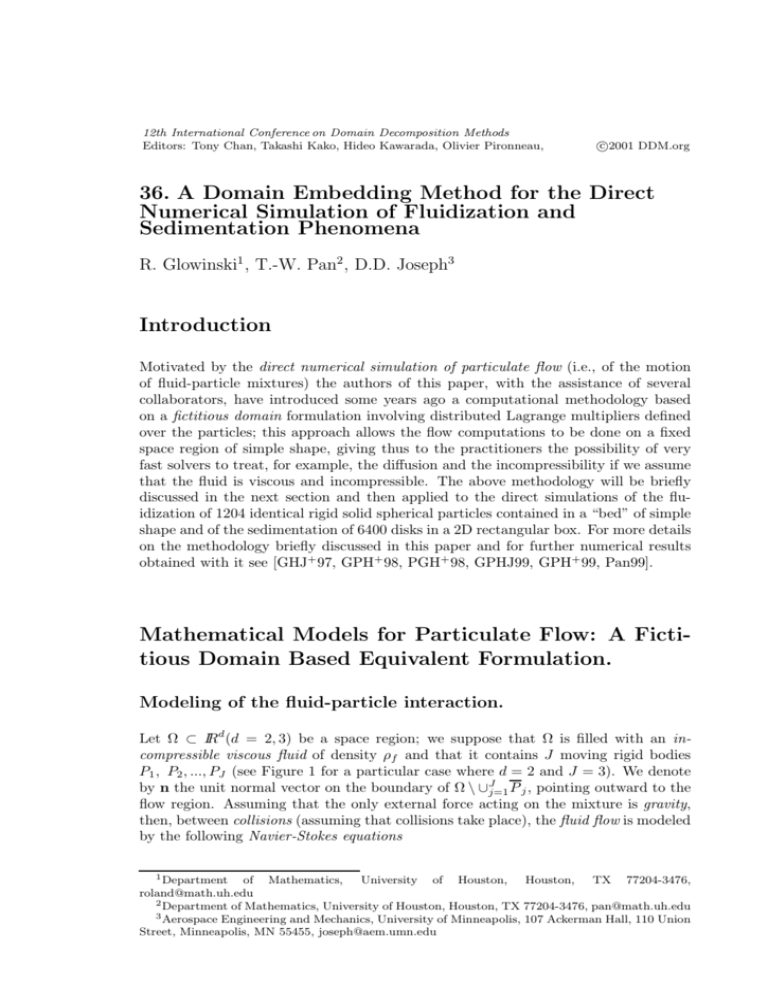
Let Ω ⊂ IRd (d = 2, 3) be a space region; we suppose that Ω is filled with an incompressible viscous fluid of density ρf and that it contains J moving rigid bodies
P1 , P2 , ..., PJ (see Figure 1 for a particular case where d = 2 and J = 3). We denote
by n the unit normal vector on the boundary of Ω \ ∪Jj=1 P j , pointing outward to the
flow region. Assuming that the only external force acting on the mixture is gravity,
then, between collisions (assuming that collisions take place), the fluid flow is modeled
by the following Navier-Stokes equations
1 Department
of Mathematics,
University of Houston,
Houston,
TX 77204-3476,
roland@math.uh.edu
2 Department of Mathematics, University of Houston, Houston, TX 77204-3476, pan@math.uh.edu
3 Aerospace Engineering and Mechanics, University of Minneapolis, 107 Ackerman Hall, 110 Union
Street, Minneapolis, MN 55455, joseph@aem.umn.edu
GLOWINSKI, PAN, JOSEPH
342
11111
00000
00000
11111
00000
11111
00000
11111
P1
00000
11111
00000
11111
00000
11111
00000
11111
Ω
1111
0000
0000
1111
0000
1111
0000
1111
P3
0000
1111
0000
1111
0000
1111
0000
1111
n
11111
00000
00000
11111
00000
11111
00000
11111
P2
00000
11111
00000
11111
00000
11111
00000
11111
Γ
Figure 1: An example of two-dimensional flow region with three particles.
∂u
J
ρf ∂t + (u · ∇)u = ρf g + ∇ · σ in Ω \ ∪j=1 Pj (t),
∇ · u = 0 in Ω \ ∪Jj=1 Pj (t),
u(x, 0) = u0 (x), ∀x ∈ Ω \ ∪Jj=1 Pj (0), with ∇ · u0 = 0,
(1)
to be completed by
u = g0 on Γ with
Γ
g0 · ndΓ = 0
(2)
and by the following no-slip boundary condition on the boundary ∂Pj of Pj
−−−−→
u(x, t) = Vj (t) + ωj (t) × Gj (t)x, ∀x ∈ ∂Pj (t),
(3)
where, in (3), Vj (resp., ωj ) denotes the velocity of the center of mass Gj (resp., the
angular velocity) of the j th particle, for j = 1, ..., J. In (1), the stress-tensor σ verifies
σ = τ − pI,
(4)
τ = 2νD(u) = ν(∇u + ∇ut ) (Newtonian case),
(5)
τ is a nonlinear f unction of ∇u (non − N ewtonian case).
(6)
typical situations for τ being
The motion of the particles is modeled by the following Newton-Euler equations
Mj dVj = Mj g + Fj ,
dt
(7)
dω
Ij j + ω j × Ij ω j = Tj ,
dt
for j = 1, ..., J, where in (7):
• Mj is the mass of the j th particle.
• Ij is the inertia tensor of the j th particle.
A DOMAIN EMBEDDING METHOD
343
• Fj is the resultant of the hydrodynamical forces acting on the j th particle, i.e.
Fj = (−1)
σnd(∂Pj ).
(8)
∂Pj
• Tj is the torque at Gj of the hydrodynamical forces acting on the j th particle,
i.e.
Tj = (−1)
−−→
Gj x × σnd(∂Pj ).
(9)
∂Pj
• We have
dGj
= Vj .
dt
(10)
Equations (7) to (10) have to be completed by the following initial conditions:
Pj (0) = P0j , Gj (0) = G0j , Vj (0) = V0j , ωj (0) = ω 0j , ∀j = 1, ..., J.
(11)
Remark 1 If the flow-rigid body motion is two-dimensional, or if Pj is a spherical
body made of an homogeneous material, then the nonlinear term ω j × Ij ω j vanishes
in (7).
A global variational formulation of the fluid-particle interaction
via the virtual power principle.
We suppose, in this section, that the fluid is Newtonian of viscosity ν. Let us denote
by P (t) the space region occupied at time t by the particles; we have thus P (t) =
∪Jj=1 Pj (t). To obtain a variational formulation for the system of equations described
as described above, we introduce the following functional space of compatible test
functions:
1
d
W0 (t) = {(v, Y, θ)|v ∈ (H (Ω \ P (t))) , v = 0 on Γ,
J
J
(12)
Y = {Yj }j=1 , θ = {θ j }j=1 , with Yj ∈ IRd , θ j ∈ IR3 ,
−−−−→
v(x, t) = Yj + θj × Gj (t)x on ∂Pj (t), ∀j = 1, ..., J};
in (12) we have θj = {0, 0, θj } if d = 2.
Applying the virtual power principle to the whole mixture (i.e., to the fluid and
the particles) yields the following global variational formulation:
∂u
ρ
+
(u
·
∇)u
·
vdx
+
2ν
D(u) : D(v)dx
f
Ω\P (t) ∂t
Ω\P (t)
J
J
−
p∇ · vdx +
Mj V̇j · Yj +
(Ij ω̇j + ωj × Ij ω j ) · θj
(13)
Ω\P (t)
j=1
j=1
J
= ρ
g · vdx +
Mj g · Yj , ∀{v, Y, θ} ∈ W0 (t),
f
Ω\P (t)
j=1
GLOWINSKI, PAN, JOSEPH
344
Ω\P (t)
q∇ · u(t)dx = 0, ∀q ∈ L2 (Ω \ P (t)),
u(t) = g0 (t) on Γ,
−−−−→
u(x, t) = Vj (t) + ω j (t) × Gj (t)x, ∀x ∈ ∂Pj (t), ∀j = 1, ..., J,
dGj
= Vj ,
dt
(14)
(15)
(16)
(17)
to be completed by the following initial conditions
u(x, 0) = u0 (x), ∀x ∈ Ω \ P (0),
(18)
Pj (0) = P0j , Gj (0) = G0j , Vj (0) = V0j , ωj (0) = ω 0j , ∀j = 1, ..., J.
(19)
In relations (13) to (19):
• We have denoted functions such as x → ϕ(x, t) by ϕ(t).
• We have used the following notation
d
a · b = k=1 ak bk , ∀a = {ak }dk=1 , b = {bk }dk=1 ,
d d
A : B = k=1 l=1 akl bkl , ∀A = (akl )1≤k,l≤d , B = (bkl )1≤k,l≤d .
• We have ω j (t) = {0, 0, ωj (t)} if d = 2.
• We assume that u(t) ∈ (H 1 (Ω \ P (t)))d and p(t) ∈ L2 (Ω \ P (t)).
A distributed Lagrange multiplier based fictitious domain method.
Following references [GHJ+ 97, GPH+ 98, PGH+ 98, GPHJ99, GPH+ 99, Pan99] we
introduce the following variant of the virtual power formulation (13)-(19):
For a.e. t > 0, find u(t), p(t), {Vj (t), Gj (t), ω j (t)}Jj=1 , such that
∂u
ρf
+ (u · ∇)u · vdx − p∇ · vdx + 2ν D(u) : D(v)dx
∂t
Ω
Ω
Ω
dVj
dω j
J
· Yj + (Ij
+ ω j × Ij ω j ) · θj
+ j=1 (1 − ρf /ρj ) Mj
dt
dt
= ρf g · vdx + J (1 − ρf /ρj )Mj g · Yj , ∀{v, Y, θ} ∈ W̃0 (t),
j=1
(20)
Ω
Ω
q∇ · udx = 0, ∀q ∈ L2 (Ω),
u = g0 on Γ,
−−−−→
u(x, t) = Vj (t) + ω j (t) × Gj (t)x, ∀x ∈ Pj (t), ∀j = 1, ..., J,
dGj
= Vj ,
dt
Pj (0) = P0j , Vj (0) = V0j , ωj (0) = ω 0j , Gj (0) = G0j , ∀j = 1, ..., J,
u(x, 0) = u0 (x), ∀x ∈ Ω \ ∪Jj=1 P0j
−−−→
u(x, 0) = V0j + ω 0j × G0j x, ∀x ∈ P0j , ∀j = 1, ..., J,
(21)
(22)
(23)
(24)
(25)
(26)
(27)
A DOMAIN EMBEDDING METHOD
345
with, in relation (20), space W̃0 (t) defined by
W̃0 (t) = {(v, Y, θ)|v ∈ (H01 (Ω))d , Y = {Yj }Jj=1 , θ = {θ j }Jj=1 , with
−−−−→
Yj ∈ IRd , θj ∈ IR3 , v(x, t) = Yj + θj × Gj (t)x in Pj (t), ∀j = 1, ..., J}.
In order to relax the rigid body motion constraint (23) we are going to employ a family
{λj }Jj=1 of Lagrange multipliers so that λj (t) ∈ Λj (t) with
Λj (t) = (H 1 (Pj (t)))d , ∀j = 1., , , .J.
(28)
We obtain, thus, the following fictitious domain formulation with Lagrange multipliers:
For a.e. t > 0, find u(t), p(t), {Vj (t), Gj (t), ωj (t), λj (t)}Jj=1 , such that
u(t) ∈ (H 1 (Ω))d , u(t) = g0 (t) on Γ, p(t) ∈ L2 (Ω),
(29)
Vj (t) ∈ IRd , Gj (t) ∈ IRd , ω j (t) ∈ IR3 , λj (t) ∈ Λj (t), ∀j = 1, ..., J,
and
∂u
ρ
+
(u
·
∇)u
·
vdx
−
p∇ · vdx
f
Ω ∂t
Ω
J
dVj
· Yj
(1 − ρf /ρj )Mj
+2ν D(u) : D(v)dx +
j=1
dt
Ω
J
dωj
+ ωj × Ij ω j ) · θj
+
(1 − ρf /ρj )(Ij
j=1
dt
J
−−→
−
< λj , v − Yj − θj × Gj x >j
j=1
J
=
ρ
g
·
vdx
+
(1 − ρf /ρj )Mj g · Yj ,
f
j=1
Ω
∀v ∈ (H 1 (Ω))d , ∀Y ∈ IRd , ∀θ ∈ IR3 ,
0
j
(30)
j
−−−−→
< µj , u(t) − Vj (t) − ω j (t) × Gj (t)x >j = 0, ∀µj ∈ Λj (t), ∀j = 1, ..., J,
(31)
completed by relations (21), (24)-(27). The two most natural choices for < ·, · >j are
defined by
(µ · v + δj2 ∇µ : ∇v)dx, ∀µ and v ∈ Λj (t),
(32)
< µ, v >j =
< µ, v >j =
Pj (t)
Pj (t)
(µ · v + δj2 D(µ) : D(v))dx, ∀µ and v ∈ Λj (t),
(33)
with δj a characteristic length (the diameter of Pj , for example). Other choices are
possible as shown in, e.g, ref. [GPHJ99].
On the discretization of problem (29)-(31).
The space approximation (resp., time discretization) of problem (29)-(31) by finite
element method (resp., operator splitting) methods is discussed in refs. [GHJ+ 97,
GPH+ 98, PGH+ 98, GPHJ99, GPH+ 99, Pan99]; the above references also include a
discussion of the numerical treatment of particle/particle and particle/boundary collisions.
GLOWINSKI, PAN, JOSEPH
346
Numerical Simulations
The Fluidization of a Bed of 1204 Particles.
We consider here the simulation of the fluidization in a bed of 1,204 spherical particles.
The computational domain is Ω = (0, 0.6858)×(0, 20.3997)×(0, 44.577). The thickness
of this bed is slightly larger than the diameter of the particles which is d = 0.635,
so there is only one layer of balls in the 0x2 direction (the above lengths are in
centimeters). In [FJL87] many experimental results related to this type of “almost twodimensional” beds are presented. The fluid is incompressible, viscous, and Newtonian;
its density is ρf = 1 and its viscosity is νf = 10−2 . We suppose that at t = 0 the fluid
and the particles are at rest. The boundary condition for the velocity field is
0
on the f our vertical walls,
0
u(t) =
5
0
on the two horizontal walls.
1 − e−50t
The density of the balls is ρs = 1.14. We suppose that the fluid can enter and leave
the bed. The mesh size for the velocity field is hΩ = 0.06858 (corresponding to 2 × 10⁶
vertices for the velocity mesh), while it is hp = 2hΩ for the pressure (corresponding
to 2.9×10⁵ vertices for the pressure mesh). The time step is ∆t = 10−3 . The initial
position of the balls is shown in Figure 2. After starting pushing the balls up, we
observe that the inflow creates cavities propagating among the balls in the bed. Since
the inflow velocity is much higher than the critical fluidization velocity (of the order
of 2.5 here), many balls are pushed directly to the top of the bed. Those balls at the
top of the bed are stable and closely packed while the others are circling around at
the bottom of the bed. Those numerical results are very close to experimental ones
obtained at the University of Minnesota and have been visualized in Figures 2 and 3
(where the lengths are in inches this time). In the simulation, the maximum particle
Reynolds number is 1,512 while the maximum averaged particle Reynolds number is
285. The computations were done on an SGI Origin 2000, using a partially parallelized
code; the computational time is approximately 110 sec./time step.
Sedimentation of 6,400 circular particles in a two-dimensional
cavity. Rayleigh-Taylor instability for particulate flow.
The test problem that we consider now concerns the simulation of the motion of 6,400
sedimenting circular disks in the closed cavity Ω = (0, 8) × (0, 12). The diameter d of
the disks is 1/12 and the position of the disks at time t = 0 is shown in Figure 4. The
solid fraction in this test case is 34.9%. The disks and the fluid are at rest a time
t = 0. The density of the fluid is ρf = 1 and the density of the disks is ρs = 1.1. The
viscosity of the fluid it νf = 10−2 . The time step is 10−3 . The mesh size for the velocity
field is hΩ = 1/192 (the velocity triangulation has thus about 3.5 × 10⁶ vertices) while
the pressure mesh size is hp = 2hΩ implying, approximately, 885,000 vertices for the
pressure triangulation. For this test problem where many particles ”move around” a
fine mesh is required essentially everywhere. The computational time per time step
A DOMAIN EMBEDDING METHOD
347
16
16
14
14
12
12
10
10
8
8
6
6
4
4
2
2
0
0
2
0
0
4
16
16
14
14
12
12
10
10
8
8
6
6
4
4
2
2
0
0
2
0
0
4
2
6
6
2
4
4
6
6
Figure 2: Fluidization of 1,204 spherical particles: positions of the particles at t = 0,
1.5, t = 3 and 4.5 (from left to right and from top to bottom).
GLOWINSKI, PAN, JOSEPH
348
16
16
14
14
12
12
10
10
8
8
6
6
4
4
2
2
0
0
2
0
0
4
16
16
14
14
12
12
10
10
8
8
6
6
4
4
2
2
0
0
2
0
0
4
2
6
6
2
4
4
6
6
Figure 3: Fluidization of 1,204 spherical particles: positions of the particles at t = 6,
7, 8 and 10 (from left to right and from top to bottom).
A DOMAIN EMBEDDING METHOD
349
Figure 4: Sedimentation of 6,400 particles: positions at t = 0, 0.4, 0.5, 0.6 (from left
to right and from top to bottom), and visualization of the Rayleigh-Taylor instability.
350
GLOWINSKI, PAN, JOSEPH
Figure 5: Sedimentation of 6,400 particles: positions at t = 2.6, 5, 9, 13 (from left to
right and from top to bottom), and visualization of the Rayleigh-Taylor instability.
A DOMAIN EMBEDDING METHOD
351
is approximately 10 min. on a DEC Alpha 500-au workstation, implying that to
simulate one time unit of the phenomenon under consideration we need, practically, a
full week. The evolution of the 6,400 disks sedimenting in Ω is shown in Figures 4 and
5. The maximum particle Reynolds number in the entire evolution is 72.64. Figure
4 clearly shows the development of a ”text-book” Rayleigh-Taylor instability. This
instability develops into a fingering phenomenon and many symmetry breaking and
other bifurcation phenomena, including drafting, kissing and tumbling, take place at
various scales and times; similarly vortices of various scales develop and for a while
the phenomenon is clearly chaotic, which is not surprising after all for a 6,400-body
problem. Finally, the particles settle at the bottom of the cavity and the fluid returns
to rest.
Acknowledgments
We acknowledge the helpful comments and suggestions of E. J. Dean, V. Girault, J.
He, T.I. Hesla, Y. Kuznetsov, J. Periaux, G. Rodin, A. Sameh, V. Sarin, and P. Singh,
and also the support of the Supercomputing Institute at the University of Minnesota
concerning the use of an SGI Origin2000. We acknowledge also the support of the
NSF (Grants ECS-9527123, CTS-9873236, and DMS-9973318) and Dassault Aviation.
References
[FJL87]A. F. Fortes, D. D. Joseph, and T. S. Lundgren. Nonlinear mechanics of
fluidization of beds of spherical particles. J. Fluid Mech., 177:467–483, 1987.
[GHJ+ 97]R. Glowinski, T. I. Hesla, D.D. Joseph, T.W. Pan, and J. Periaux. Distributed Lagrange multiplier methods for particulate flows. In M.O. Bristeau, G.J.
Etgen, W. Fitzgibbon, J.L. Lions, J. Periaux, and M.F. Wheeler, editors, Computational Science for the 21st Century, pages 270–279, Chichester, 1997. Wiley.
[GPH+ 98]R. Glowinski, T.W. Pan, T.I. Hesla, D.D. Joseph, and J. Periaux. A fictitious domain method with distributed Lagrange multipliers for the numerical simulation of particulate flow. In J. Mandel, C. Farhat, , and X.C. Cai, editors, Domain
Decomposition Methods 10, pages 121–137, Providence, RI, 1998. AMS.
[GPH+ 99]R. Glowinski, T. W. Pan, T. I. Hesla, D. D. Joseph, and J. Periaux. A
distributed Lagrange multiplier/fictitious domain method for flows around moving
rigid bodies: Application to particulate flow. Int. J. Numer. Meth. Fluids, 30:1043–
1066, 1999.
[GPHJ99]R. Glowinski, T.W. Pan, T.I. Hesla, and D.D. Joseph. A distributed Lagrange multiplier/fictitious domain method for particulate flow. International Journal of Multiphase Flow, 25:755–794, 1999.
[Pan99]T. W. Pan. Numerical simulation of the motion of a ball falling in an incompressible viscous fluid. C. R. Acad. Sci. Paris, 327, Série 2, b:1035–1038, 1999.
[PGH+ 98]T. W. Pan, R. Glowinski, T. I. Hesla, D. D. Joseph, and J. Periaux. Numerical simulation of the Rayleigh-Taylor instability for particulate flow. In M. Hafez
and J. C. Heinrich, editors, Proceedings of the Tenth International Conference on
Finite Elements in Fluids, pages 217–222, 1998.


