Using Wire less Ethernet for Localization
advertisement
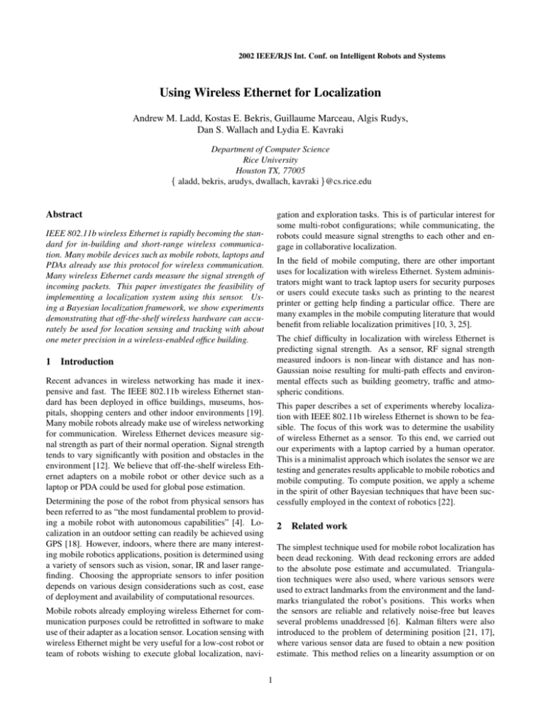
2002 IEEE/RJS Int. Conf. on Intelligent Robots and Systems Using Wireless Ethernet for Localization Andrew M. Ladd, Kostas E. Bekris, Guillaume Marceau, Algis Rudys, Dan S. Wallach and Lydia E. Kavraki Department of Computer Science Rice University Houston TX, 77005 aladd, bekris, arudys, dwallach, kavraki @cs.rice.edu Abstract gation and exploration tasks. This is of particular interest for some multi-robot configurations; while communicating, the robots could measure signal strengths to each other and engage in collaborative localization. IEEE 802.11b wireless Ethernet is rapidly becoming the standard for in-building and short-range wireless communication. Many mobile devices such as mobile robots, laptops and PDAs already use this protocol for wireless communication. Many wireless Ethernet cards measure the signal strength of incoming packets. This paper investigates the feasibility of implementing a localization system using this sensor. Using a Bayesian localization framework, we show experiments demonstrating that off-the-shelf wireless hardware can accurately be used for location sensing and tracking with about one meter precision in a wireless-enabled office building. In the field of mobile computing, there are other important uses for localization with wireless Ethernet. System administrators might want to track laptop users for security purposes or users could execute tasks such as printing to the nearest printer or getting help finding a particular office. There are many examples in the mobile computing literature that would benefit from reliable localization primitives [10, 3, 25]. The chief difficulty in localization with wireless Ethernet is predicting signal strength. As a sensor, RF signal strength measured indoors is non-linear with distance and has nonGaussian noise resulting for multi-path effects and environmental effects such as building geometry, traffic and atmospheric conditions. 1 Introduction Recent advances in wireless networking has made it inexpensive and fast. The IEEE 802.11b wireless Ethernet standard has been deployed in office buildings, museums, hospitals, shopping centers and other indoor environments [19]. Many mobile robots already make use of wireless networking for communication. Wireless Ethernet devices measure signal strength as part of their normal operation. Signal strength tends to vary significantly with position and obstacles in the environment [12]. We believe that off-the-shelf wireless Ethernet adapters on a mobile robot or other device such as a laptop or PDA could be used for global pose estimation. This paper describes a set of experiments whereby localization with IEEE 802.11b wireless Ethernet is shown to be feasible. The focus of this work was to determine the usability of wireless Ethernet as a sensor. To this end, we carried out our experiments with a laptop carried by a human operator. This is a minimalist approach which isolates the sensor we are testing and generates results applicable to mobile robotics and mobile computing. To compute position, we apply a scheme in the spirit of other Bayesian techniques that have been successfully employed in the context of robotics [22]. Determining the pose of the robot from physical sensors has been referred to as “the most fundamental problem to providing a mobile robot with autonomous capabilities” [4]. Localization in an outdoor setting can readily be achieved using GPS [18]. However, indoors, where there are many interesting mobile robotics applications, position is determined using a variety of sensors such as vision, sonar, IR and laser rangefinding. Choosing the appropriate sensors to infer position depends on various design considerations such as cost, ease of deployment and availability of computational resources. 2 Related work The simplest technique used for mobile robot localization has been dead reckoning. With dead reckoning errors are added to the absolute pose estimate and accumulated. Triangulation techniques were also used, where various sensors were used to extract landmarks from the environment and the landmarks triangulated the robot’s positions. This works when the sensors are reliable and relatively noise-free but leaves several problems unaddressed [6]. Kalman filters were also introduced to the problem of determining position [21, 17], where various sensor data are fused to obtain a new position estimate. This method relies on a linearity assumption or on Mobile robots already employing wireless Ethernet for communication purposes could be retrofitted in software to make use of their adapter as a location sensor. Location sensing with wireless Ethernet might be very useful for a low-cost robot or team of robots wishing to execute global localization, navi1 0.35 0.35 Probability of Registering Strength 0.4 Probability of Registering Strength 0.4 0.3 0.25 0.25 0.2 0.15 0.2 0.15 0.1 0.05 0 0 0.3 0.1 0.05 32 64 96 128 160 Signal Strength 192 224 0 0 32 64 96 128 160 Signal Strength 192 224 Figure 1: Two examples of signal strength distributions, measured over time at a constant location. the existence of a good linearization. Arguably the most powerful algorithms to date are based on Bayesian inference, in particular Markov models [15, 8] and Monte Carlo localization [7, 23]. Various discretization schemes can be employed but often occupancy grids and point sets are employed. If no usable theoretical model is available, conditional probability distributions can be sampled directly. Alternately, the environment can be modeled with a topological map, e.g., as a generalized Voronoi graph [2]; localization in this paradigm is based on identifying nodes in the graph from geometric environmental information [16]. The literature in this field is vast but other works offer an overview of current techniques [14, 22]. The current paper is an example of a Bayesian approach. We sample the space, we measure the signal strength at regularly spaced locations and explicitly integrate the probability distribution. Localization is a problem that has been also explored in the wireless community for a wireless device like a laptop computer, usually carried by a human operator, is localized. Many systems have been implemented that use specialized hardware [24, 20]. The RADAR system [1], however, uses only the 802.11b wireless networking for localization. The algorithmic approach in RADAR is mainly based in nearest neighbor heuristics and triangulation techniques, similar to early work in the robotics community for robot localization. The authors report localization accuracy of within 3 meters of their actual position with about fifty percent probability. While our work has similar design goals to RADAR, we have taken a very different approach. 3 RF Signal Propagation in Wireless Ethernet The IEEE 802.11b standard uses radio frequencies in the 2.4GHz band, which is license-free around the world. The available adapters are based on spread spectrum radio technology so that interference on a single frequency does not block the signal [5]. Accurate prediction of signal strength is a complex and difficult task since the signal propagates by unpredictable means [19]. Due to reflection, refraction, scattering and absorption of radio waves by structures inside a building, the transmitted signal most often reaches the receiver by more than one path, resulting in a phenomenon known as multi- path fading [12]. In the 2.4GHz frequency band, microwave ovens, BlueTooth devices, 2.4 GHz cordless phones and welding equipment can be sources of interference. Finally, 2.4GHz is a resonating frequency of water and consequently people absorb signal. Noise is introduced via sensitivity to atmospheric parameters and interference. The signal components arriving from indirect paths and the direct path, if this exists, combine and produce a distorted version of the transmitted signal. The received signal varies according to time and the relative position of the transmitter and receiver. Fortunately, signal profiles tend to remain approximately the same over short distances [12]. Although efforts have been made to model radio signal distribution in an indoor environment [9, 19], different experiments have arrived at different distributions and a general model remains unavailable. Experiments held in several office buildings have shown good log-normal fit [11, 9]. The parameters for the model tends to be difficult to learn in practice, limiting the value of these models [19]. Our experiments verified this; we concluded that log-normal fits were only feasible when line-of-sight between transmitter and receiver existed. In our experiments, the noise distributions of signal strength measured at a fixed location varied greatly. In Figure 1, we show two typical examples of the signal. Although there is a dominant mode, we observed the distributions were asymmetric and multi-modal, in other words non-Gaussian. 4 Methodology Hardware Our experiments were conducted by a human operator carrying a HP OmniBook 6000 laptop with a PCMCIA LinkSys wireless Ethernet card. This particular card uses the Intersil Prism2 chipset. We modified the standard Linux kernel driver for this card to support a number of new functionalities: the scanning and recording of hardware MAC addresses and signal strengths of packets, using promiscuous mode, and the automatic scanning of base stations. We needed a constant source of signal from all base stations for optimum results. Unfortunately, this meant we could not simply be a passive observer. While we could simply put the network interface adapter into promiscuous mode and listen were Apple AirPort base stations and were mounted between two and three meters off the ground. We had a fairly precise map of the building that we had processed to mark off free space and obstacles. The pixel resolution was roughly six centimeters in this map. Our Model The localizer that we implemented operates in the general framework of Bayesian inference localization [22, 8, 15]. We chose a state space and observation space, estimated the required conditional probability distributions and explicitly integrated. Figure 2: Map of Duncan Hall. to all packets being transmitted by base stations, this can only guarantee a stream of packets from one base station: the one that the card is currently associated with. While base stations do send out beacon packets several times a second, the hardware we were using did not give us access to this signal. Instead, we were forced to use the base station probe facility of 802.11b [13]. Client nodes can broadcast a probe request packet on a wireless network. Base stations that receive such a request respond with a probe response packet. The client then collects these packets and, judging by the strengths of the incoming signals, can determine the closest base station to connect to. We analyze these signal strengths to determine our location relative to the base stations. Our initial experiments consisted of logging signal strengths at various positions in the building, where the experiments took place, to characterize the behavior of the hardware we were using. A given base station can appear anywhere between zero and four times in the packets the firmware returned to us. For each packet, we are given an -bit signal strength. It is interesting to note that unless the sender is very close to the receiver, signals in the top half of this range rarely occur. Certain other signal strengths simply never occur. The lowest order bit tends to be very noisy. When compared to other sensors, such as sonar, this signal is very thin: at most 5 usable bits of signal per packet. Building Geometry We operated on the third floor of Duncan Hall at Rice University, in the four hallways shown in Figure 2. The two longer hallways (hallways 1 and 2) measure 105 feet, and the two shorter hallways (hallways 3 and 4) measure 56 feet. Hallway 1 has a base station near one end, and hallway 2 has a base station really close to the middle. Hallways 3 and 4 are notable in that they are open above and either partially (in the case of hallway 4) or totally (in the case of hallway 3) open on the sides. There were nine base stations on this floor. The base stations We chose various sets of points in the map for the state space. A point for our experiments was chosen as a tuple on the floor of the building our experiments took place in. There is no indication that doing this in would be any harder although we never did this experiment. To summarize, our state space consisted of a set of points ! " . Our observation space consisted of the observations that occurred in a single measurement from our base station scanner. A packet consists of # pairs of base station MAC address and signal strength. A single measurement consists of a count # of the number of base station / signal pairs, a summary of the frequency counts (the number of times each known base station was seen in this measurement) and then the # pairs. We denote this as a vector $%'&(# *) +*)-,'+/. "0 1+2.34*053687 , where # is the count, 9 is total number of base stations, ): is the frequency count for the ; th base station, ."< is base station index of the = th measurement and 0>< is the signal strength at that point. At each point : , we take a sample of the observables. For each base station we build two histograms at that point. The first is a distribution of the frequency counts over the sampled observations. The second is a distribution of signal strengths. Based on this sample, we can calculate two kinds of conditional probability ?A@42)<BDCFE :/ , the probability that the frequency counts for the = th base station is C when we are at state : and ?A@420 < E . < : , the probability . < has signal strength 0 < at state : . For that the base station $G'&H#F*) +*) 2. *0 +/. 3 *0 3 I7 , we compute MN ?A@42$JE O MN , :KL <!P ?A@Q/)+<QE O :2KSU R T <!P 3 ?A@4204<4E .!<6 :VKRSW By explicitly integrating a probability distribution of position based on a received measurement and selecting a representative point we obtain a position estimate. After trying several possible schemes, we decided to solve a global localization problem for each measurement rather than keep a running estimate because each measurement usually contains enough information to get a good guess of our position. We used uniform distributions as our prior distribution before each measurement and selected the point of maximum probability assuming that the point exceeds a certain threshold probability. The resulting stream can be further processed to improve precision as discussed in following section. Sensor Fusion with a Hidden Markov Model The second filter that we implemented takes the output of the inference engine as a stream of timed observations and tries to stabilize the distribution by noting that a person carrying a laptop typically does not move very quickly. This sort of calculation could be achieved with a much higher degree of precision using odometry from a mobile robot. We model a moving operator trying to track her position as a hidden Markov model (HMM). We use a more finely discretized state space than the Bayesian inference engine and try to interpolate our position out of the stream of measurements coming from this filter. This design decision was made after noticing that naive averaging of the filter produced results with twice the precision we expected for points we had not taken any training samples at. For our purposes, an HMM is a set of states X + , a set of observations YZ $ !$-[\ , a conditional probability 0^]>`_aYcbed fJ+gh , and a transition probability matrix i . As in the Bayesian inference engine, each state is a point j ! . The transition probability matrix semantics describe how the system being modeled evolves with time. In this case, it describes how a person travels through the state space. If k is a i probability distribution over , then kl5 k is the probability distribution after some discrete time step. The idea is that the random state change occurs “hidden” from the observer. The observation function 0 has semantics identical to observa tion in the Bayesian inference of position. 0j !$6mn?A@4$JE , the probability of observing $ while at . As each observation arrives, 0 is used to update the probability of being in a i given state in , and then is used to transition states. If i 0 accurately models the behavior of the inference engine and accurately models the behavior of a person transitioning from state to state, the sensor fusion will have superior results to Bayesian inference alone. i In our case was chosen to heuristically model human motion. The scheme we described could be implemented far more precisely by making use of a dead reckoning sensor and modeling the system as a partially observable Markov decision process (POMDP). By employing one of several variant algorithms in the literature [22], significantly more accurate position tracking could be achieved for a mobile robot. 5 Results In this section we describe several experiments which try to objectively measure the precision and reliability of using wireless Ethernet for localization. Training Process Our system was trained by taking samples at various points in the world by three different operator. Each operator, had to hold a laptop, to stand still for several seconds at each sample point to do this. We assume that sampled data was operator independent, that is to say that we believed that measured distributions would be relatively un- affected by who took the data. The amount of data taken at each point is varied adaptively according to a simple heuristic which measures the rate of convergence to a stable distribution. Once the sampled distribution at each visible base station had converged beyond a threshold, we halt the process. This allowed us to adaptively determine how much sampling is necessary as a function of variation in the signal. In our case, usual sampling times ranged from ten seconds to about a minute. Static Localization in a Hallway We describe experiments executed in hallway 1 on the map in Figure 2, which was sampled in two different orientations at every 5 feet. The purpose of this is to test the precision of the Bayesian inference localizer. Timed tests occur at various positions and facing both orientations in the hallway and bulk statistics are calculated. The training data was taken by two different operators, with each operator training the localizer in one of the two orientations. All experiments were executed by a third operator. We measured a total of 1307 packets on 11 different positions and for both orientations. The positions were spread every 10 feet to be exhaustive. The algorithm reported back positions discretized to 5 feet. In Figure 3, we show the cumulative probability of obtaining error less than a given distance. We have observed that error is within gpo meters with probability f>pqq . Experiments with HMM Approach We attempted to improve these results by implementing a more sophisticated sensor fusion based on a hidden Markov model (HMM). The HMM ran at a higher discretization than the Bayesian inference engine. The state transitions were heuristically chosen to be a reasonable model of human motion. We then walked round-trips of the four hallways in our test area, as shown on the map in Figure 2. The quality of the results varied depending on the geometry of the building. For example, areas adjacent to large open spaces tended to be noisier. Figure 4 and Figure 5 show tracking experiments that took place in two of the hallways. The operator walked the hallway varying speed and periodically recording the time certain predefined markers were passed. The operator attempted to keep constant speed between markers. In the figures, we report both the Bayesian inference static localization results and the HMM fused results. In the top figure, a significant improvement is obtained and, overall, the results are excellent. In the bottom figure, the signal was much noisier due to a large open area adjacent to the hall and relatively poor base station placement. Note that in both cases, errors of g o m are still roughly within one standard deviation. 6 Conclusions In our experiments, we can measure and track position robustly with 1.5 meters of error distributed within a standard deviation. We used the Intersil Prism2 chipset for our wireless Ethernet cards and Apple AirPorts as base stations, both read- Cumulative Probability 1 0.75 0.5 0.25 0 1 2 3 4 5 Error (m) 6 7 8 9 10 Figure 3: Bulk cumulative error distribution for 1307 packets over 22 poses in a hallway localized using the position of maximum probability as calculated by direct application of Bayes’ rule. 600 1 Actual Position Sensor Fusion Static Localization 0.9 Sensor Fusion Static Localization 0.8 Cumulative Probability 500 0.7 400 Position 0.6 300 0.5 0.4 200 0.3 0.2 100 0.1 0 0 10 20 30 40 Time 50 60 70 0 0 80 1 2 3 4 5 Error (m) 6 7 8 Figure 4: Tracking a round-trip walk of hallway 1 in our test area (see Figure 2 the building map). Measured error for the track, shown on the right graph, is within one meter with probability f> rs , an improvement of sQot over static localization. This improvement is illustrated in the actual tracking performance, shown in the left graph. 300 1 Actual Position Sensor Fusion Static Localization 0.9 Sensor Fusion Static Localization 0.8 Cumulative Probability 250 0.7 200 Position 0.6 150 0.5 0.4 100 0.3 0.2 50 0.1 0 0 10 20 Time 30 40 50 0 0 1 2 3 4 5 Error (m) 6 7 8 9 10 Figure 5: Tracking a round-trip walk of hallway 4 in our test area (see Figure 2 the building map). While sensor fusion provided some improvement, it was not significant due more pathological behavior of static localization in certain regions. ily available and inexpensive hardware. The building we operated in had fairly complicated geometry and the base stations were laid out more than a year before we began our work. The base station layout was chosen for communication reliability reasons. The experiments were conducted by human operators which introduced error due to signal absorption and lack of odometry. Nevertheless, the results are valid for localization carried with different hardware or with a mobile robot. In fact, similar experiments carried out with a robot would likely be significantly more precise as we avoid absorption errors induced by the operator and have odometry as an additional sensor. In this paper, we provide strong evidence that reliable localization with wireless Ethernet can be achieved. Acknowledgements Andrew Ladd is partially supported by FCAR 70577, by NSF-IRI-970228 and a Whitaker grant. Kostas Bekris is partially supported by NSF-IRI-970228. Algis Rudys is supported by NSF-CCR-9985332. Dan Wallach is supported by an NSF Career Award CCR-9985332, an NSF Special Projects Award ANI-9979465, and a Texas ATP award. Lydia Kavraki is supported by NSF Career Award IRI970228, a Whitaker grant, a Texas ATP award and a Sloan Fellowship. The authors would like to thank Moez AbdelGawad and Skye Schell for their help with taking measurements. They would also like to thank Dave Johnson for his advice and comments. References [1] P. Bahl and V. Padmanabhan. User Location and Tracking in an In-Building Radio Network. Technical Report MSR-TR-99-12, Microsoft Research, 1999. [2] H. Choset and K. Nagatani. Topological Simultaneous Localization and Mapping (SLAM): Toward Exact Localization Without Explicit Localization. IEEE Transactions on Robotics and Automation, 17(2):125–137, April 2001. [3] T. W. Christ and P. A. Godwin. A Prison Guard Duress Alarm Location System. In Proc. IEEE International Carnahan Conference on Security Technology, October 1993. [4] I. Cox. Blanche - an Experiment in Guidance and Navigation of an Autonomous Robot Vehicle. IEEE Transactions on Robotics and Automation, 7(2):193–204, 1991. [5] T. Cutler. Wireless Ethernet and how to use it. The Online Industrial Ethernet Book, Issue 5, 1999. [6] G. Dudek and M. Jenkins. Computational Principles of Mobile Robotics. Cambridge University Press, 2000. [7] D. Fox, W. Burgard, F. Dellaert, and S. Thrun. Monte Carlo Localization: Efficient Position Estimation for Mobile Robots. In Proc. of the Sixteenth National Conference on Artificial Intelligence (AAAI-99), pages 343–349, Orlando, Florida, 1999. [8] D. Fox, W. Burgard, and S. Thrun. Markov Localization for Mobile Robots in Dynamic Environments. Journal of Artificial Intelligence Research, (JAIR), 11:391–427, November 1999. [9] P. Harley. Short Distance Attenuation Measurements at 900MHz and 1.8GHz Using Low Antenna Heights for Microcells. IEEE Journal on Selected Areas in Communications (JSAC), 7(1):5– 11, January 1989. [10] A. Harter, A. Hopper, P. Steggles, A. Ward, and P. Webster. The Anatomy of a Context-Aware Application. In Proc. of the 5th Annual ACM/IEEE International Conference on Mobile Computing and Networking (MOBICOM 1999), pages 59–68, Seattle, Washington, August 1999. [11] H. Hashemi. Impulse Response Modeling of Indoor Radio Propagation Channels. IEEE Journal on Selected Areas in Communications (JSAC), 11:967–978, September 1993. [12] H. Hashemi. The Indoor Radio Propagation Channel. Proc. of the IEEE, 81(7):943–968, July 1993. [13] Institute of Electrical and Electronics Engineers, Inc. ANSI/IEEE Standard 802.11: Wireless LAN Medium Access Control (MAC) and Physical Layer (PHY) Specifications, 1999. [14] H. E. J. Borenstein and L. Feng. Navigating Mobile Robots. A. K. Peters, Ltd., Wellesley, Massachusetts, 1996. [15] K. Konolige and K. Chou. Markov Localization using Correlation. In Proc. of the Seventeenth International Joint Conference on Artificial Intelligence (IJCAI), pages 1154–1159, Seattle, Washington, August 1999. [16] B. Kuipers and Y. T. Byan. A robot exploration and mapping strategy based on a semantic hierarcy of spatial representations. Journal on Robotics and Automatic Systems, 8:47–63, 1991. [17] J. F. Leonard and H. Durrant-Whyte. Mobile Robot Localization by Tracking Geometric Beacons. IEEE Transactions Robotics and Automations, 7(3):376–382, June 1991. [18] T. Logsdon. Understanding the Navstar: GPS, GIS and IVHS. Second edition. Van Nostrand Reinhold, New York, 1995. [19] A. Neskovic, N. Nescovic, and G. Paunovic. Modern Approaches in Modeling of Mobile Radio Systems Propagation Environment. IEEE Communications Surveys, Third Quarter 2000. [20] N. Priyantha, A. Chakraborty, and H. Balakrishman. The Cricket Location Support System. In Proc. of the 6th Annual ACM/IEEE International Conference on Mobile Computing and Networking (MOBICOM 2000), pages 32–43, Boston, Massachusetts, August 2000. [21] R. Smith and P. Cheeseman. On the Representation of Spatial Uncertainty. Journal of Robotics Research, 5(4):56–68, 1987. [22] S. Thrun. Probabilistic Algorithms in Robotics. AI Magazine, 21(4):93–109, 2000. [23] S. Thrun, D. Fox, W. Burgard, and F. Dellaert. Robust Monte Carlo Localization for Mobile Robots. Artificial Intelligence, 101:99–141, 2000. [24] A. Ward, A. Jones, and A. Hopper. A new location technique for the active office. IEEE Personal Communications, 4(5):42–47, October 1997. [25] J. Werb and C. Lanzl. Designing a positioning system for finding things and people indoors. IEEE Spectrum, 35(9):71–78, September 1998.
