Demolition of
concrete structures
Bringing it down—safely
BY HAL T. HUDGINS
PRESIDENT
HUDGINS & COMPANY, INC.
DEMOLITION SPECIALISTS
ATLANTA, GEORGIA
T
he demolition contractor is a
specialist in wrecking or destroying buildings safely. With
careful planning, he can make the
job look easy, and by selecting the
right demolition method he also
makes the job profitable.
Most contractors, even though
not demolition specialists, will have
to demolish portions of stru c t u re s
as part of their repair and remodeling business. Knowing which
method or combination of methods
to use for demolition of reinforced
or prestressed concrete stru c t u re s
is essential for a safe and profitable
job.
Because of the difficulty of estimating the costs of demolition of
concrete, the general contractor is
usually well-advised to engage the
services of a competent demolition
contractor when his job requires a
significant amount of demolition.
Selection of the best method or
methods depends partly on time
and money available and on the
surrounding environment. The following discussion of methods used
is based primarily on my own experience, but I have also relied upon
the experience of others and data
provided by manufacturers of demolition equipment.
Ball and crane
This is one of the oldest and most
commonly used methods for building demolition. A crane uses a
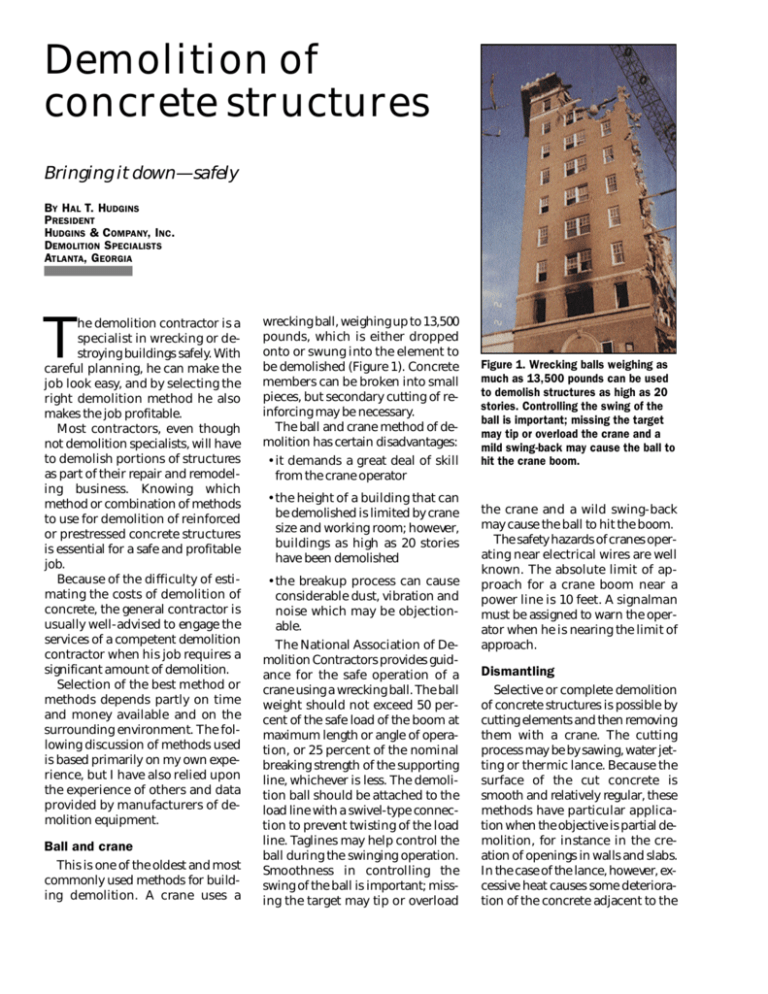
wrecking ball, weighing up to 13,500
pounds, which is either dropped
onto or swung into the element to
be demolished (Figure 1). Concrete
members can be broken into small
pieces, but secondary cutting of reinforcing may be necessary.
The ball and crane method of demolition has certain disadvantages:
• it demands a great deal of skill
from the crane operator
• the height of a building that can
be demolished is limited by crane
size and working room; howe ve r,
buildings as high as 20 stories
have been demolished
• the breakup process can cause
considerable dust, vibration and
noise which may be objectionable.
The National Association of Demolition Contractors provides guidance for the safe operation of a
crane using a wrecking ball. The ball
weight should not exceed 50 percent of the safe load of the boom at
maximum length or angle of operation, or 25 percent of the nominal
breaking strength of the supporting
line, whichever is less. The demolition ball should be attached to the
load line with a swivel-type connection to prevent twisting of the load
line. Taglines may help control the
ball during the swinging operation.
Smoothness in controlling the
swing of the ball is important; missing the target may tip or overload
Figure 1. Wrecking balls weighing as
much as 13,500 pounds can be used
to demolish structures as high as 20
stories. Controlling the swing of the
ball is important; missing the target
may tip or overload the crane and a
mild swing-back may cause the ball to
hit the crane boom.
the crane and a wild swing-back
may cause the ball to hit the boom.
The safety hazards of cranes operating near electrical wires are well
known. The absolute limit of approach for a crane boom near a
power line is 10 feet. A signalman
must be assigned to warn the operator when he is nearing the limit of
approach.
Dismantling
Selective or complete demolition
of concrete structures is possible by
cutting elements and then removing
them with a crane. The cutting
process may be by sawing, water jetting or thermic lance. Because the
surface of the cut concrete is
smooth and relatively regular, these
methods have particular application when the objective is partial demolition, for instance in the creation of openings in walls and slabs.
In the case of the lance, howe ve r, excessive heat causes some deterioration of the concrete adjacent to the
Figure 2. A special 72-inch-diameter saw was manufactured
to dismantle the 33-inch-thick
beams of this cantilevered skywalk. Each dismantled segment weighs 7 tons.
cut. Whatever the method used, the
cutting process isolates a particular
element so that it may be lowered to
the ground for further breakup or
transportation to the dump site.
Most objectives of controlled demolition can be achieved using
standard concrete sawing techniques and equipment, including
diamond tipped blades to cut reinforcement. Specialized saws may be
developed to handle unusual projects (Figure 2). Although sawing
produces negligible vibration and
dust, it may be noisy and require
equipment to supply and clean up
the large quantity of water used to
cool the saw.
Concrete up to 3 feet thick may be
cut with an abrasive water jet. The
heart of the abrasive-water-jet cutting system is a small nozzle in
which water is pre s s u ri zed up to
60,000 psi and combined with solid
a b ra s i ves to create a high-velocity
cutting jet. Cutting with a water jet
minimizes dust and eliminates vibration and fire hazards. An abrasive and water-catching system is
required to clean up during the jetting process.
The water jet can be used not only for cutting straight lines but also
contours, a useful feature for cutting
access manholes. Straight-line cut
rates on the order of 1 inch penetration per minute are possible for reinforced concrete slabs.
A thermic lance is created by
packing a seamless mild steel tube
with low carbon rods and passing
oxygen through the tube. Once the
lance is ignited, fusion will take
place creating a temperature between 4000 and 7000 degrees F
which is capable of burning through
concrete up to 12 feet thick. A 2inch-diameter horizontal hole can
be bored in concrete at a typical rate
of 2 to 3 inches per minute.
The presence of reinforcing steel
is an advantage for thermic demolition, since this provides extra steel
that can be oxidized to melt the conc re t e. Work may also be facilitated
by following the path of re i n f o rc ement. While this method eliminates
vibration and dust problems, it creates other hazards associated with
smoke and fire danger.
Whether sawing, jetting or lancing is used to dismantle the structure or its components, each element must be safely lowered to the
ground. Lifting hooks or special rigging should be adequately secured
to dismantled members. If existing
lifting hooks or loops are found to
be in good condition then they
should be used.
d e l i ve ring 100 to 20,000 footpounds of energy at a frequency of
300 to 800 blows per minute (Figure
3). The advantages of a machinemounted breaker may include a
telescoping boom for easy reach
and maneuve ra b i l i t y, remote control operation and underwater demolition capabilities. Some of the
smaller remote-controlled machines can be lifted through window
openings and used inside a building
to demolish floors and walls.
Productivity can vary greatly depending on hammer size, type of
concrete, amount of reinforcing and
working conditions. For unreinforced concrete, breakout rates may
be as low as 10 cubic yards to as high
as 1000 cubic yards per 8-hour day.
Breakout rates for reinforced concrete (larger hammer required for
reinforced versus unreinforced concrete) vary from 13 to 750 cubic
yards per 8-hour day. The Dodge
Public Works and Cost Guide indicates a productivity of 12 cubic
yards per 8-hour day using handheld breakers (jackhammers).
Machine-mounted breakers are
usually noisy, generate dust and vibration and may be restricted in areas of limited work space. To keep
vibrations at a safe level, one Corps
of Engineers office places a 150 footpound limit on the hammer energy
Pneumatic and hydraulic
breakers
A common piece of equipment
used for demolishing bridge decks,
foundations and pavements is a hydraulically or pneumatically operated, boom-mounted breaker. Although small hand-operated
breakers are still used, in many cases they have been replaced by machine-mounted breakers capable of
Figure 3. A boom-mounted remotecontrolled hydraulic breaker reduces
the slab section prior to lifting with a
crane. The slab section has been
sawn free on two sides while it rested
on shoring.
Figure 4. The demolition of reinforced
concrete requires that both the
concrete and bond between the
concrete and steel be broken. The
splitter can be used on reinforced
concrete walls to break pieces at a
45-degree angle, providing access to
cut the reinforcing steel.
allowed for concrete removal on its
locks and dams.
Pressure bursting
This method of demolition can be
classified into two categories, mechanical and chemical bursting.
Pressure bursting with mechanical
tools is fairly inexpensive, quiet, and
doesn’t cause vibration; but the
drilling of holes for the insertion of
the splitter does produce noise and
vibration. This can be overcome by
coring the holes with a diamondtipped coring machine, but at far
greater cost.
Mechanical bursting is done with
a hand-held splitting machine that
operates on hydraulic pressure provided by a small motor. The splitting
end of the device is a steel wedge or
plug positioned between two hard
metal shims called feathers. Holes
ranging from 1 to 2 inches in diameter are drilled into the concrete.
The wedge is inserted into the hole
and the subsequent hydraulic pressure forces the wedge against the
two feathers.
Forces as high as 410 tons can be
exerted against the feathers, which
expand and force the concrete to
split. Controlling the crack direction
and the movement of the demolished mass may be difficult using
mechanical bursting tools. Additionally, when reinforced concrete is
being split, it is almost always necessary to utilize a hydraulic or pneumatic breaker, either hand-held or
machine-mounted to expose the reinforcing bars for cutting. Figure 4
shows how to use a splitter to break
a reinforced concrete wall.
Although they are more costly,
chemicals may be preferred for
p re s s u re bursting. An expansive
agent when correctly mixed will undergo a large increase in volume
over a period of time. By placing the
expansive slurry into boreholes that
are located in a predetermined pattern, concrete can be split in a controlled manner for removal (Figure
5). Within 10 to 20 hours, cracks are
generated by an expansive pressure
that can exceed 4300 psi.
The chemical agent is formulated
to be used at a certain temperature;
any deviation from this temperature
will reduce the expected expansive
p re s s u re. Freezing the chemical
agent will greatly reduce its effectiveness.
Explosives
Blasting methods employ rapidly
expanding gases confined within a
series of boreholes to produce controlled fractures which provide for
easy concrete removal. In general,
blasting methods are efficient
means of removing large volumes of
distressed or deteriorated concrete.
But, due to dangers inherent in handling and usage, blasting is considered most dangerous and re q u i re s
more stringent controls than any
other methods of demolition.
For the demolition of concrete
structures it is usual to drill holes at
a predetermined angle into the concrete to be removed. The holes are
then charged with an explosive
which is electrically detonated. Empirical judgment based on the skill
and experience of the operator is
the basis for blasting design. Recent
advances in blasting design include
the utilization of recognized formulas and calculations which determine the position, angle and depth
of the borehole, as well as the size of
the charge.
Figure 5. This bridge pier was cracked
by nonexplosive demolition material,
an expansive powder added to water
and poured into predrilled holes.
A simpler but far less effective
method of blasting is to lay the explosive charge on the element to be
demolished and cover it with sandbags. Another method, particularly
useful for containers, is to fill the
s t ru c t u re with water and detonate
an explosive charge which has been
suspended at the center. The water
transmits shock waves to the surrounding walls. Shaped charges for
the directional cutting of elements
are also available.
Explosives are versatile and have
great flexibility in terms of work output. Howe ve r, excessive ground vibration may damage adjacent structures and air blast may cause
superficial damage such as window
breakage elsewhere. The National
Association of Demolition Contractors states that the use of explosives
to demolish entire buildings or portions thereof shall not be permitted
unless there is sufficient clear space
in all directions equal to 75 percent
of the height of the building being
demolished. Precautions should be
taken to stop flying debris and in all
circumstances strict site control
must be maintained to ensure the
safety of workers and the general
public.
Safety checklist
Whatever the demolition method
chosen, or the size of the job, safety
is of prime importance. Fo l l ow i n g
are some key factors to consider.
Services. Gas, water, electricity
and other services to the structure
must be properly capped where
necessary. Electricity or other lines
needed to aid demolition must be of
approved heavy-duty construction
and must be kept adequately protected along a known path.
Access. All movements of people
within the structure should be along
designated routes, that is, through
agreed doorways and stairways, or
along specially constructed walkways with fixed ladders. Removal of
debris should also follow an agreed
route. All other openings, horizontal
and vertical, should be blocked off
completely to avoid danger from
falling material. Even openings
needed for debris removal should
be blocked when not in use.
Loadings. Demolition may seriously change loadings from those
for which the structure was originally designed. Any wall or floor that
will be required to carry the excess
weight of stored material, or which
will be subject to undue pressure
from waste, must be adequately
shored to withstand the extra loading. At no time should debris be allowed to accumulate to a weight
greater than a floor can carry. High
impact loads from falling debris can
be another source of unsafe loading. In general, no area of wall or
slab greater than 10 square feet
should be allowed to fall on any
floor at one time. The lower walls of
a building within which waste is allowed to pile up are particularly susceptible to the effects of a destructive loading for which they were not
designed. Wind loadings must also
be considered. Under no circum-
stances should walls be left standing overnight if they are not plumb
and strong enough to resist toppling
by wind pressure. If wall stability is
questionable, demolition should
continue down to the nearest structural cross member, or temporary
shoring should be erected. In general, no section of wall more than one
story high should be left standing
unsupported at any time unless it
was specifically designed to stand
higher.
Structural members. When demolishing a structure from the top
down, no supports at a lower level
should be cut or removed until demolition at the upper level is complete. Particular care should be exercised in removing load-bearing
beams and columns which tie into
party walls. When beams and
columns are cut they should always
be well secured with wire rope or
chains. If a large amount of debris
is expected it may be desirable to increase the volume of ground-floor
space into which waste can be
dumped.
Worker protection. Workers must
always stand on a firm base while
carrying out demolition. Free ends
of cut members may be needed as
work platforms and must therefore
be shored.
Other hazards. All glass and combustible material should be removed from a structure before demolition begins. Removal of
asbestos and polyc h l o ri n a t e d
biphenyls (PCBs) must be done in
accordance with regulations set by
the Occupational Safety and Health
Act (OSHA) and the Environmental
Protection Agency (EPA). Each of
these materials can be extremely
dangerous to workers.
PUBLICATION #C870024
Copyright © 1989, The Aberdeen Group
All rights reserved
Demolition of
Prestressed Concrete
Demolishing prestressed concrete structures can be more difficult than demolishing reinforced
concrete because of the energy
stored in the prestressing tendons.
Prestressing tendons are like
stretched rubber bands, with energy stored in the stretching process.
The release of the stored energy in
a rubber band causes it to sail
through the air. Likewise, the release of stored energy in a prestressing tendon may cause it to
sail through the air—as a dangerous missile—threatening the lives
of workers. While a rubber band
carries only small forces, a prestressing tendon commonly transmits forces in excess of 125,000
pounds.
Methods of prestressing
Two basic methods of prestressing are in use:
• Pre-tensioning, in which the
steel is tensioned before the concrete is cast, transfers the prestressing force to the concrete by
bond.
• Post-tensioning, in which the
tendons are tensioned after the
concrete has been cast and allowed to harden, transfers the prestressing force by means of end
anchors.
Pre-tensioning is used primarily
for factory-made units. These may
be subsequently post-tensioned
on site with additional tendons.
Generally post-tensioning is applied to cast-in-place concrete in
which ducts are formed within the
members. The tendons are inserted in these ducts and then stressed
and permanently anchored.
Post-tensioned tendons can be
bonded or unbonded. After the
tendon is inserted into the duct,
the space between the tendon and
duct may be grouted for the full
length of the member. This grouting bonds the tendon to the duct
and the surrounding concrete,
hence the name bonded. Tendons
for which the duct is filled with
grease (to prevent corrosion)
rather than grout are considered
unbonded.
Demolition of prestressed pretensioned structures
The total demolition of a prestressed pre-tensioned structure is
no more difficult than the demolition of a cast-in-place re i n f o rc e d
concrete structure. Pre s t re s s e d
pre-tensioned members are usually designed to resist applied loading in only one direction. Because
of this, the members will fail rather
easily if a force can be applied in
an opposite or lateral direction.
The partial demolition of a prestressed pre-tensioned structure
requires more care than a similar
operation on a cast-in-place structure. More attention must be given to proper placement of adequate shoring, careful rigging and
lifting, and the avoidance of impact loads to the structure below.
Pre-tensioned slabs and beams, or
smaller dismantled portions, may
be lifted and lowered to the ground
as complete units (Photo A). Gene ra l l y, any necessary shoring and
subsequent lifting should be from
points near the ends of the units.
Demolition of prestressed
post-tensioned structures
The total demolition of a prestressed post-tensioned structure
presents a very different problem,
Photo A. Sections of this precast,
prestressed double tee unit were
shored, sawed and lifted out.
The demolition of prestressed
structures requires a thorough
understanding of the
fundamentals of prestressing.
The underside of this slab
illustrates the prestressing
force released by cutting the
tendons. Shoring is in place as
a safety precaution.
particularly if the tendons are unbonded. As this is a relatively new
type of construction, few post-tensioned buildings have been demolished. Safe, uneventful demolition of relatively low stru c t u re s
using a crane and a ball has been
accomplished where there is adequate surrounding work space.
Howe ve r, the majority of experienced contractors and engineers
familiar with the problems and potential dangers of post-tensioned
structures suggest that they be dismantled a floor at a time. This is
true whether the structure is of
cast-in-place concrete with subsequent post-tensioning, or of precast, prestressed members which
were also post-tensioned.
Disassembly or from-the-topdown demolition requires a large
amount of shoring which must be
installed along the entire length of
the members, unless intermediate
tendon anchors were installed
during construction. Once shored,
the slab and beams can be detensioned—in reverse order in which
they were tensioned. Then the
slabs and beams can be demolished using those methods previously described, with the exception of the ball-and-crane method.
Partial demolition of post-tensioned structures
The partial demolition of an unbonded post-tensioned structure
can be very complicated and haza rd o u s. If “as-built” drawings are
not available, this operation can be
even more complex. The original
s t ru c t u re drawings are used as a
guide for the proper placement of
shoring under each member.
After the shoring is in place, the
tendon and reinforcing bars
are located using magnetic detection devices. Once this is done,
careful drilling, chipping or sawing
may be used to expose the prestressing tendons (Photo B). Then
a hydraulic tensioning device is
used to detension the tendon, releasing its force and allowing the
concrete member to rest on the
shoring.
The concrete can then be broken
with either hand-held or machinemounted breakers, or once completely severed, reduced to a size
which may be lifted and lowe re d .
Because the concrete may contain
no reinforcing steel, or only top reinforcing, the section must be
rigged such that it can be lifted and
lowered without causing the concrete section to rupture from its
own dead weight.
Careful planning by competent
persons experienced in post-tensioning is essential before attempting partial demolition of
post-tensioned structures.
Photo B. Detensioning the tendon
releases its force and allows safe
removal of post-tensioned concrete
sections. Here a laborer is chipping
grout out of an anchorage pocket to
allow access for a hydraulic

