Can an Ohmmeter Test Thyristors and Triacs?
advertisement

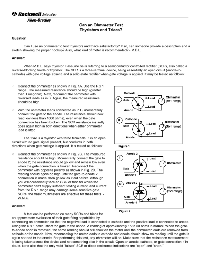
Can an Ohmmeter Test Thyristors and Triacs? Question: Can I use an ohmmeter to test thyristors and triacs satisfactorily? If so, can someone provide a description and a sketch showing the proper hookup? Also, what kind of meter is recommended? - M.B.L. Answer: When M.B.L. says thyristor, I assume he is referring to a semiconductor controlled rectifier (SCR), also called a reverse-blocking triode or thyristor. The SCR is a three-terminal device, being essentially an open circuit (anode-tocathode) with gate voltage absent, and a solid-state rectifier when gate voltage is applied. It may be tested as follows: • Connect the ohmmeter as shown in Fig. 1A. Use the R x 1 range. The measured resistance should be high (greater than 1 megohm). Next, reconnect the ohmmeter with reversed leads as in B. Again, the measured resistance should be high. • With the ohmmeter leads connected as in B, momentarily connect the gate to the anode. The resistance should now read low (less than 1000 ohms), even when the gate connection has been broken. The SCR resistance instantly goes again high in both directions when either ohmmeter lead is lifted. The triac is a thyristor with three terminals. It is an open circuit with no gate signal present, but conducts in both directions when gate voltage is applied. It is tested as follows: • Connect the ohmmeter as shown in Fig. 2C. The measured resistance should be high. Momentarily connect the gate to anode 2; the resistance should go low and remain low even when the gate connection is broken. Reconnect the ohmmeter with opposite polarity as shown in Fig. 2D. The reading should again be high until the gate-to-anode 2 connection is made, then go low as it did before. Although you will occasionally face an SCR or triac for which the ohmmeter can't supply sufficient testing current, and current from the R x 1 range may damage some sensitive-gate SCRs, the basic multimeters are effective for these tests. W.M.C. Answer: A test can be performed on many SCRs and triacs for an approximate evaluation of their gate firing capabilities by connecting an ohmmeter, so that the negative lead is connected to cathode and the positive lead is connected to anode. Using the R x 1 scale, short the gate to the anode. A reading of approximately 15 to 50 ohms is normal. When the gateto-anode short is removed, the same reading should still show on the meter until the ohmmeter leads are removed from cathode or the anode. Now, reconnecting the meter leads to cathode and anode should show no reading until the gate is again shorted to the anode. For performing this test, any ohmmeter will do. Make sure that the resistance measurement is being taken across the device and not something else in the circuit. Open an anode, cathode, or gate connection if in doubt. Note also that the only valid “failure" SCR or diode resistance indications are “open" and "short.” The anode-cathode or gate cathode measurement must show a short (0 resistance) in both directions (forward and reverse polarity) for a device to be considered "shorted" and infinite resistance in both directions for an “open." A diode normally shows low resistance in the forward direction and high resistance when the VOM probes are reversed. Hence, the VOM can be a check on diode polarity. The SCR normally has a high resistance across the anode-cathode in both directions. For a SCR to be open, the gate-cathode must also show open. - J.E.R. Answer: To test a triac: connect ohmmeter to pins No. 1 and 2 as shown in Fig. 3. Set ohm scale to x 1 or x 10. The meter should read near infinity. This indicates the power circuit is "off." Next, install temporary jumper between pins No. 2 and 3. Meter should drop to zero or very low. This indicates the power circuit is closed. Another handy test is to connect 120V AC (or less) as shown in Fig. 3B. The lamp should go on and off, depending on the position of the jumper. The test for a thyristor is essentially the same as for the triac except that the triac will conduct in either direction, while the thyristor conducts only in the “forward" position. I have used the above “quick and dirty” tests many times. Fig. 4 shows a typical packaging arrangement and symbols for a triac and a thyristor. Sometimes pin No. 2 is connected internally to the metal tab, and this simplifies making terminal connection. This can be checked with the ohmmeter. Almost any type of multimeter should be satisfactory. - W.L.F.


