Rubber-Metal Bonding as an Electrochemical
advertisement
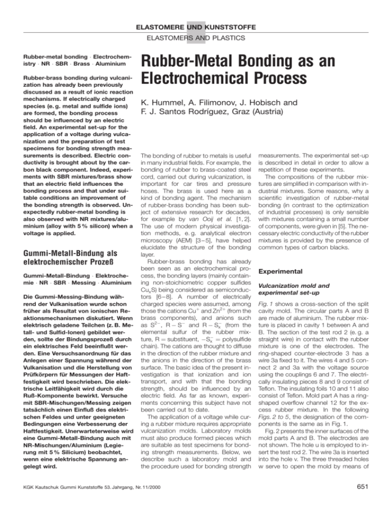
ELASTOMERE UND KUNSTSTOFFE ELASTOMERS AND PLASTICS Rubber-metal bonding Electrochemistry NR SBR Brass Aluminium Rubber-brass bonding during vulcanization has already been previously discussed as a result of ionic reaction mechanisms. If electrically charged species (e. g. metal and sulfide ions) are formed, the bonding process should be influenced by an electric field. An experimental set-up for the application of a voltage during vulcanization and the preparation of test specimens for bonding strength measurements is described. Electric conductivity is brought about by the carbon black component. Indeed, experiments with SBR mixtures/brass show that an electric field influences the bonding process and that under suitable conditions an improvement of the bonding strength is observed. Unexpectedly rubber-metal bonding is also observed with NR mixtures/aluminium (alloy with 5 % silicon) when a voltage is applied. Gummi-Metall-Bindung als elektrochemischer Prozeû Gummi-Metall-Bindung Elektrochemie NR SBR Messing Aluminium Die Gummi-Messing-Bindung waÈhrend der Vulkanisation wurde schon fruÈher als Resultat von ionischen Reaktionsmechanismen diskutiert. Wenn elektrisch geladene Teilchen (z. B. Metall- und Sulfid-Ionen) gebildet werden, sollte der Bindungsprozeû durch ein elektrisches Feld beeinfluût werden. Eine Versuchsanordnung fuÈr das Anlegen einer Spannung waÈhrend der Vulkanisation und die Herstellung von PruÈfkoÈrpern fuÈr Messungen der Haftfestigkeit wird beschrieben. Die elektrische LeitfaÈhigkeit wird durch die Ruû-Komponente bewirkt. Versuche mit SBR-Mischungen/Messing zeigen tatsaÈchlich einen Einfluû des elektrischen Feldes und unter geeigneten Bedingungen eine Verbesserung der Haftfestigkeit. Unerwarteterweise wird eine Gummi-Metall-Bindung auch mit NR-Mischungen/Aluminium (Legierung mit 5 % Silicium) beobachtet, wenn eine elektrische Spannung angelegt wird. Rubber-Metal Bonding as an Electrochemical Process K. Hummel, A. Filimonov, J. Hobisch and F. J. Santos RodrõÂguez, Graz (Austria) The bonding of rubber to metals is useful in many industrial fields. For example, the bonding of rubber to brass-coated steel cord, carried out during vulcanization, is important for car tires and pressure hoses. The brass is used here as a kind of bonding agent. The mechanism of rubber-brass bonding has been subject of extensive research for decades, for example by van Ooij et al. [1, 2]. The use of modern physical investigation methods, e. g. analytical electron microscopy (AEM) [3 ± 5], have helped elucidate the structure of the bonding layer. Rubber-brass bonding has already been seen as an electrochemical process, the bonding layers (mainly containing non-stoichiometric copper sulfides Cux S) being considered as semiconductors [6 ± 8]. A number of electrically charged species were assumed, among those the cations Cu and Zn2 (from the brass components), and anions such as S2ÿ , R ÿ Sÿ and R ÿ Sÿ x (from the elemental sulfur of the rubber mixture, R substituent, ÿSÿ x polysulfide chain). The cations are thought to diffuse in the direction of the rubber mixture and the anions in the direction of the brass surface. The basic idea of the present investigation is that ionization and ion transport, and with that the bonding strength, should be influenced by an electric field. As far as known, experiments concerning this subject have not been carried out to date. The application of a voltage while curing a rubber mixture requires appropriate vulcanization molds. Laboratory molds must also produce formed pieces which are suitable as test specimens for bonding strength measurements. Below, we describe such a laboratory mold and the procedure used for bonding strength KGK Kautschuk Gummi Kunststoffe 53. Jahrgang, Nr. 11/2000 measurements. The experimental set-up is described in detail in order to allow a repetition of these experiments. The compositions of the rubber mixtures are simplified in comparison with industrial mixtures. Some reasons, why a scientific investigation of rubber-metal bonding (in contrast to the optimization of industrial processes) is only sensible with mixtures containing a small number of components, were given in [5]. The necessary electric conductivity of the rubber mixtures is provided by the presence of common types of carbon blacks. Experimental Vulcanization mold and experimental set-up Fig. 1 shows a cross-section of the split cavity mold. The circular parts A and B are made of aluminium. The rubber mixture is placed in cavity 1 between A and B. The section of the test rod 2 (e. g. a straight wire) in contact with the rubber mixture is one of the electrodes. The ring-shaped counter-electrode 3 has a wire 3a fixed to it. The wires 4 and 5 connect 2 and 3a with the voltage source using the couplings 6 and 7. The electrically insulating pieces 8 and 9 consist of Teflon. The insulating foils 10 and 11 also consist of Teflon. Mold part A has a ringshaped overflow channel 12 for the excess rubber mixture. In the following Figs. 2 to 5, the designation of the components is the same as in Fig. 1. Fig. 2 presents the inner surfaces of the mold parts A and B. The electrodes are not shown. The hole u is employed to insert the test rod 2. The wire 3a is inserted into the hole v. The three threaded holes w serve to open the mold by means of 651 Rubber-Metal Bonding as an . . . Fig. 1. Mold for the application of a voltage to the vulcanization mixture, cross-section. screw bolts after curing the rubber mixture. Fig. 3 illustrates the crown-like shape of the electrode 3. The gaps allow the rubber mixture to flow across the electrode 3 at the start of the vulcanization process before a coherent polymer network is formed. Fig. 4 explains the principal set-up of the complete arrangement for curing. The mold parts A and B are placed between the additional aluminium parts C and D which contain an electrically insulated hollow space to cover the wires 4 and 5, and the couplings 6 and 7. E and F are the heating plates of a laboratory press. The couplings 6 and 7 and the parts C and D were only used for investigations Fig. 2. Mold for the application of a voltage to the vulcanization mixture, inner surfaces of the mold parts A and B. with metal rods (diameter > 0:5 mm). For experiments with thinner wires, they were not necessary. In this case, the wires were longer and bent rectangularly at the outer surface of the mold parts A and B, covered with an electrically insulating heat-resistant material, and directed out of the mold through channels cut into the outer surface of A and B. Preparation of the test specimens The rubber mixtures were prepared on a laboratory mill. The test rod 2 and the counter-electrode 3 were inserted into mold part A. In order to ensure the complete filling of the available space, a slight excess of rubber mixture was cut into small pieces and placed into cavity 1, also between the electrodes 2 and 3. The correct filling of the mold with the vulcanization mixture was important for reliable results. Mold part B was put on part A. Subsequently parts A and B were pressed together. The couplings 6 and 7 (connected to wires 4 and 5) were fixed on test rod 2 and wire 3a. Parts C and D were fitted as depicted in Fig. 4. Parts A to D were pressed together under a clamping pressure of 30 kN between the plates E and F of the heating press. Then the voltage was applied. The vulcanization was carried out with preset values of temperature and reaction time. It was found in preliminary experiments that the effect of the electric current on the bonding strength has an optimum at a certain voltage and current density (current/surface of the electrode) of the test rod. It was also observed that an optimum polarity of the electrodes exists (test rod anode or cathode, depending on the metal). Measurements Fig. 3. Counterelectrode: (a) from the side, (b) from above. 652 A test specimen made with the set-up described in Figs. 1 to 4 is shown in Fig. 5 (a). The vulcanizate 13 with the test rod 2 was obtained in the shape of cavity 1. The counter-electrode 3 together with the wire 3a was not removed from 13 for the determination of bonding strength. The main advantage of this type of test specimen is that the samples can be pre- KGK Kautschuk Gummi Kunststoffe 53. Jahrgang, Nr. 11/2000 Rubber-Metal Bonding as an . . . Fig. 4. Application of a voltage to the vulcanization mixture, arrangement for curing. pared and tested even with non-industrial equipment and with rather small quantities of materials. It might be seen as disadvantage that the contact interface between vulcanizate and metal is small so that the standard deviation of the average of the bonding strength values is larger than that obtained with the usual standardized bonding strength measurement methods. The principle of these measurements is explained with Fig. 5(b). The test sample, compare Fig. 5(a), is covered with two circular aluminium discs 14 and 15 which are kept in their position at the levels m and n with a special clamping device which is fixed to a stable support. The lower disc 14 has two holes x and y for the rod 2 and the wire 3a, respectively. The upper disc 15 has a hole z for rod 2. The diameters of the holes x and z should be large enough to avoid friction between the rod 2 and the discs 14 and 15. The diameter of the hole z exerts a certain influence on the results of the bonding strength measurements and should be well-defined. The upper end of rod 2 is connected to a tension testing machine by the clamping device 16. The arrow d shows the direction of tension. Before measurement, the specimens were stored for about 20 h at 20 8C. Subsequently, the test rod 2 was pulled out at a rate of 100 mm/min. The strength p at the moment of tearing out was measured in N. The interface f between vulcanizate and test rod gave the bonding strength b p=f in MPa. Fig. 5. Measurement of the bonding strength with the test specimens made in the mold in Figs. 1 to 4: (a) test specimen, (b) principle of the measurements. Rubber mixes and test specimens Experiments concerning rubber-brass bonding were carried out with styrenebutadiene rubber (SBR). Because the SBR 1712 used already contained 37.5 parts of mineral oil per 100 g of polymer, all further additives were calculated for 137.5 parts by weight of SBR 1712, see Tab. 1. The brass-coated steel cord was a standard product commonly used in rubber industry and employed as received. It had a diameter of 0.25 mm. The length of the wire in contact with the rubber mixture was 5.2 mm. Accordingly contact interface was 4:08 mm2 . In bonding strength measurements, the hole z in disc 15, see Fig. 5(b), had a diameter of 1.0 mm. Experiments concerning rubber-aluminium bonding were carried out with natural rubber (NR). The mixture given in Tab. 1 uses NR-RSS3. It was shown in preliminary experiments that the tear resistence of wires consisting of pure aluminium was lower than the bonding strength achieved with the application of a voltage. Therefore experiments with rods consisting of an aluminium alloy (ªAlSi5º) containing 5 % silicon, < 0:4 % iron and < 0:16 % titanium are described. The rods were cleaned by pretreatment with emery cloth and treatment with an aqueous solution of sodium hydroxide (3 % w/v) for five minutes at room temperature, followed by washing with water and acetone. The AlSi5 rods had a diameter of 1.2 mm. The part of KGK Kautschuk Gummi Kunststoffe 53. Jahrgang, Nr. 11/2000 the rod in contact with the rubber mixture was 4.0 mm long. The contact interface was ca. 16 mm2 . In bonding strength measurements, the hole z in the disc 15 in Fig. 5(b) had a diameter of 2.0 mm. Results and discussion The examples 1 to 6 listed in Tab. 1 were investigated. Each series of experiments was carried out with a sufficiently large number of test specimens, prepared under identical conditions, to obtain a reliable average (arithmetic mean). The results are given in Tab. 2. Bonding of styrene-butadiene rubber (SBR) vulcanizates to brass-coated steel In example 1, experiments were carried out with 40 samples prepared under identical conditions to obtain the average. The cure time was the rheometrically determined tc 90 time [9] of 37 min at 150 8C. In the first series of experiments, the samples were cured without the application of a voltage. The result was a bonding strength b with an average of 4.3 MPa and a standard deviation of s 2:62 MPa. For brass-coated steel, this is a rather low bonding strength. Rupture occurred between the rubber and brass-coated steel interface and not in the rubber phase which is the case with satisfactory bonding. In a second series, a DC voltage of 6 V was applied. Better results were obtained when the 653 Rubber-Metal Bonding as an . . . Table 1. Rubber mixes (parts by weight) example 1 2 3 4 a b c rubber carbon black SBR 1712 (137.5) ª NR-RSS3 (100.0) ª 5 ª 6 ª N 234 (84.7) N 375 (84.7) N 115 (50.0) N 234 (50.0) N 121 (50.0) CD 2041 (50.0) softener sulfur accelerator a mineral oil (24.2) ª S, powder (2.06) ª DCBSC (2.06) ª mineral oilb (10.0) ª S, powder (6.40) ª DCBSC (2.40) ª ª ª ª ª ª ª aromatic naphthenic N,N-dicyclohexyl-2-benzothiazolsulfenamide test rod was the anode as opposed to being the cathode. A maximum current of ca. 200 mA was observed. A bonding strength b with the average of 13.74 MPa and a standard deviation of s 1:36 MPa were found under these conditions. Rupture occurred within the rubber phase and the wire remained coated with rubber. For example 2, the experimental procedure corresponded to that in example 1. The cure time tc 90 was 35 min at 150 8C. The first set of samples were again cured without the application of a voltage. The average value of the bonding strength b was 5.07 MPa. The standard deviation was s 1:29 MPa. In a second set of experiments, a DC voltage of 10 V was applied which corresponded to a maximum current of ca. 50 mA. The average bonding strength b was 9.75 MPa with a standard deviations s 2:64 MPa. The experiments confirm that the rubber-brass bonding under consideration is influenced by an electric field. A possible consequence of this could be changes in the bonding layer structures. However, tentative investigation of bonding to brass-coated steel cord by means of AEM did not give unequivocal evidence of differences in the bonding layers obtained in the absence (i) and presence (ii) of an electric field. Bonding layers were extracted parallel to the brass surface by chemical etching as described previously [4]. AEM showed the usual phases of non-stoichiometric copper sulfides Cux S and no striking differences between (i) and (ii) were found. Bonding of natural rubber (NR) vulcanizates to an aluminium alloy with 5 % Si For example 3, the cure time tc 90 was 7 to 8 min at 150 8C. Considering the time for heating up the model to 150 8C at the beginning of the reaction, a somewhat longer cure time of 10 min was chosen. The 27 samples cured without the application of a voltage had a bonding Table 2. Rubber-metal bonding, effect of an electric fielda a b c example metal bonding strength (MPa) without voltage with voltage 1 2 3 4 5 6 brassb ª AlSi5c ª ª ª 4.30 5.07 1.48 1.36 1.24 1.35 13.74 9.75 7.50 5.56 5.55 6.98 For the composition of the reaction mixtures see Table 1. Voltage values, standard deviation of the bonding strength and other experimental details see text. brass-coated steel cord aluminium with 5% silicon 654 strength with an average value of 1.48 MPa. The standard deviation was s 0:91 MPa. In a comparative series, a DC voltage of 8 V was applied. In this case the test rod was the cathode as this polarity gave the best results. The maximum current was between 100 and 200 mA. After 35 measurements, the average of bonding strength b was found to be 7.50 MPa with a standard deviation s 1:48 MPa. There was almost no bonding of the counter-electrode 3, also consisting of aluminium, to the vulcanizate. This can be explained with the lower current density at electrode 3, which has a much larger surface area than electrode 1. For examples 4 to 6, the experimental procedure was identical with example 3 except that voltages up to 14 V were applied. All the results indicated that in all cases a significant increase in bonding strength was obtained after the application of a voltage during vulcanization. A preliminary investigation by means of transmission electron microscopy (TEM) showed no bonding layer comparable to the copper sulfide layers found in brass bonding. A formation of Al2 S3 from Al and S is only known for high temperature reactions. Concluding remarks The principal result of these investigations is that the bonding strength obtained in rubber-metal bonding can be improved (in the case of brass) or even made possible (in the case of aluminium) by applying an electric field during vulcanization under suitable conditions. Attempts to connect this electrochemical rubber-metal bonding with possible changes in bonding layers were unsuccessful. The question is whether or not these results are in line with the present knowledge of rubber-metal bonding. Most models of rubber-brass bonding consider three phases: rubber bulk, ªbonding layerº, and brass bulk. The bonding layer (e. g. with a total thickness > 50 nm) contains various copper sulfides and zinc sulfide. Unsatisfactory bonding has been thought to occur if this bonding layer is missing or is too thick (e. g. > 500 nm). Investigations of crosssections perpendicular to the brass surface have completed this picture [4, 5]. KGK Kautschuk Gummi Kunststoffe 53. Jahrgang, Nr. 11/2000 Rubber-Metal Bonding as an . . . The chemical composition of small areas of the cross-sections was determined by means of energy-dispersive X-ray spectroscopy (EDXS). Crystal structures were identified by means of selected area electron diffraction (SAED). Further investigation methods such as electron energy-loss spectrometry (EELS), convergent beam electron diffraction (CBED), and electron spectroscopic imaging (ESI) were applied. Various morphological structures of the bonding layers could be distinguished. The simplest structure of a bonding layer cross-section, found in transmission electron microscopy (TEM) investigations [5], is shown schematically in Fig. 6. The rubber bulk is seen as the bright area R and the brass bulk as the dark area B. Between R and B there are two sublayers; neighboring R a dark one (termed D), and neighboring B a narrow bright one (termed E); d is the thickness of the sublayer. The combination of D and E has been observed in most cross-sections. D contains copper sulfides and zinc sulfide. E contains more zinc than D, and the copper content is lower than in D (both elements in the form of sulfides and oxides). It was shown that the rubber phase does not end between R and D (level g) but nearly reaches to the brass surface (level h). The rubber near the brass surface contains polysulfide chains, and is thought to be a kind of ªcementº for all sublayers. A suitable model of rubber-metal bonding observed after the application References [1] W.J. van Ooij, Rubber Chem. Technol., 51 (1978) 52. [2] W.J. van Ooij, Giridhar and J.H. Ahn, Kautsch. Gummi Kunstst., 44 (1991) 348. [3] T. Kretzschmar, F. Hofer, K. Hummel and F. Sommer, Kautsch. Gummi Kunstst., 46 (1993) 710. [4] F. Hofer, G. Grubbauer, K. Hummel and T. Kretzschmar, J. Adhesion Sci. Technol., 10 (1996) 473. [5] K. Hummel, F. Hofer and T. Kretzschmar, J. Adhesion Sci. Technol., 10 (1996) 461. [6] G. Haemers, Adhesion (Barking, England), 4 (1980) 175. [7] G. Haemers, Rubber World, Sept. 1980, 26. [8] W.J. van Ooij, Rubber Chem. Technol., 57 (1984) 421. [9] DIN 53529,2; DIN-VDE-Taschenbuch Bd. 47, Kautschuk u. Elastomere 1, Beuth Verlag GmbH, Berlin, KoÈln 1988. Acknowledgements Fig. 6. Schematic drawing of a simple bonding layer in rubber-brass bonding cross-section perpendicular to the brass surface [5]. R rubber; D, E sublayers; B brass; g, h interfaces. of an electric field is that this bonding is attributable to changes in interface h between rubber and metal, and that the changed areas have a size below the resolution of routine TEM and AEM, this means at a molecular scale. The practically unchanged Cux S layers in the rubber-brass bonding case, and the occurrence of rubber aluminium bonding (where sulfide layers of the Cux S type are not possible) are consistent with this model. KGK Kautschuk Gummi Kunststoffe 53. Jahrgang, Nr. 11/2000 We thank Prof. Dr. F. Sommer (Semperit Technische Produkte GmbH, Wimpassing, Austria) for support, G. Lehr (Technical University Graz) for his assistance in the construction of vulcanization molds and measurement devices, and Dr. V. Nigmatullin (presently at Technical University Graz) for carrying out measurements by means of electron microscopy. The authors The authors performed these investigations at the Institute for Chemical Technology of Organic Materials (ICTOS) of the Technical University Graz. Dr. Klaus Hummel is em.o.Univ.-Prof., Dr. Andrej Filimonov (Moscow) was a guest scientist at ICTOS, Ing. Josefine Hobisch is member of the ICTOS staff, Dr. Francisco J. Santos RodrõÂguez finished his chemistry studies at the Industrial University of Santander (Colombia) and his doctoral thesis at ICTOS. Corresponding author Dr. K. Hummel Institut fuÈr Chemische Technologie Organischer Stoffe der Technischen UniversitaÈt Graz Stremayrgasse 16/1 A-8010 Graz 655

