FIHR ™
Software for the simulation, troubleshooting and operations of gas or oil fired process
heaters.
Overview
FIHR™ is a simulation program for fireboxes and convection sections of fired process heaters. In
simulation mode, it can used for troubleshooting, such as identification of tube burnout, and operation,
to identify the best operating conditions given changes in feedstock or product specifications.
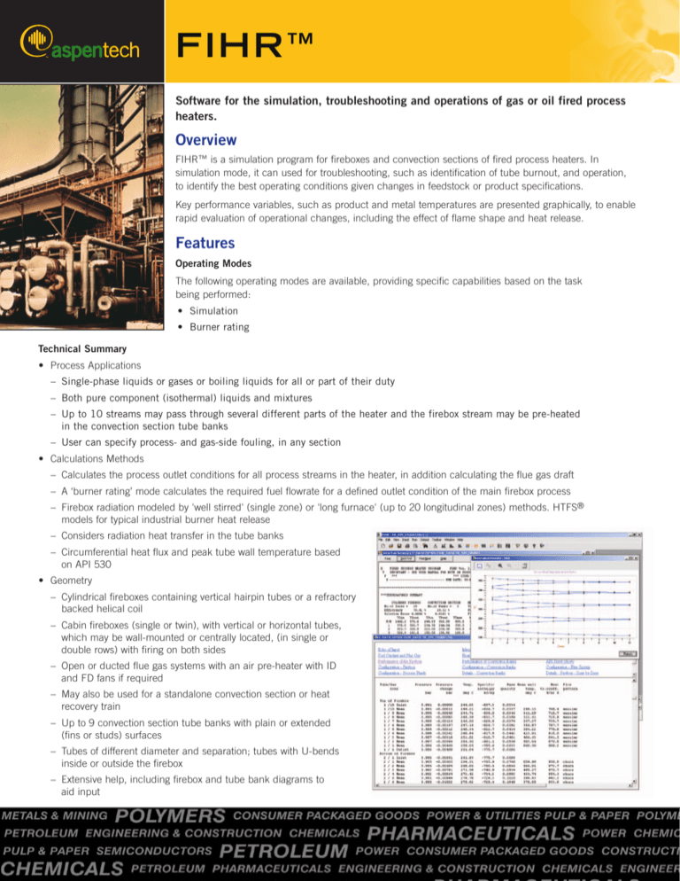
Key performance variables, such as product and metal temperatures are presented graphically, to enable
rapid evaluation of operational changes, including the effect of flame shape and heat release.
Features
Operating Modes
The following operating modes are available, providing specific capabilities based on the task
being performed:
• Simulation
• Burner rating
Technical Summary
• Process Applications
– Single-phase liquids or gases or boiling liquids for all or part of their duty
– Both pure component (isothermal) liquids and mixtures
– Up to 10 streams may pass through several different parts of the heater and the firebox stream may be pre-heated
in the convection section tube banks
– User can specify process- and gas-side fouling, in any section
• Calculations Methods
– Calculates the process outlet conditions for all process streams in the heater, in addition calculating the flue gas draft
– A ‘burner rating’ mode calculates the required fuel flowrate for a defined outlet condition of the main firebox process
– Firebox radiation modeled by 'well stirred' (single zone) or 'long furnace' (up to 20 longitudinal zones) methods. HTFS®
models for typical industrial burner heat release
– Considers radiation heat transfer in the tube banks
– Circumferential heat flux and peak tube wall temperature based
on API 530
• Geometry
– Cylindrical fireboxes containing vertical hairpin tubes or a refractory
backed helical coil
– Cabin fireboxes (single or twin), with vertical or horizontal tubes,
which may be wall-mounted or centrally located, (in single or
double rows) with firing on both sides
– Open or ducted flue gas systems with an air pre-heater with ID
and FD fans if required
– May also be used for a standalone convection section or heat
recovery train
– Up to 9 convection section tube banks with plain or extended
(fins or studs) surfaces
– Tubes of different diameter and separation; tubes with U-bends
inside or outside the firebox
– Extensive help, including firebox and tube bank diagrams to
aid input
• Output
– Summary of heater performance
– API fired heater datasheet
– Detailed thermal analysis of each part of the heater
including, estimate of maximum metal temperatures,
process-side film and tube wall temperatures
– Graphical output of process and flue gas temperature,
heat transfer rate, process temperature, tube metal
temperature profiles, heat transfer coefficient variation
and draft
• Program integration – link to HYSYS® and Aspen Plus™
Benefits
• Improved design – FIHR is a comprehensive, easy-to-use tool
for the design of fired process heaters. Its use enables the
more efficient design of new heaters and cost-effective
revamp studies. It can also augment or replace in-house tools
that are difficult to use and expensive to maintain and update.
• Improved process operations – Links to process simulators
allow the effect of phenomena such as pre-heat exchanger
fouling, to be properly evaluated. Major operational savings
can be made with the use of a comprehensive heater model
based on sound firebox radiation modeling providing a
rational basis for day-to-day optimization of plant performance
with changing product specifications, feedstock changes. The
rigorous modeling of FIHR is vital for proper investment
appraisal where retrofit process modifications are proposed
to optimize product yields.
• Increased engineering efficiency – In many processes,
operation of fired heaters can be a limiting step, as these are
often run at the practical limit of firebox tube temperature. In
a reactor charge heater, one customer was able to use FIHR
to explore a range of fouling assumptions. He developed a
relationship between stack temperature and a safe working
limit for the tubes and was able to predict the throughput
reduction with time. This enabled the cleaning cycle to be
optimized for throughput versus downtime and decoke costs,
resulting in savings of several hundred thousand dollars.
worldwide headquarters
Aspen Technology, Inc.
Ten Canal Park
Cambridge, MA 02141-2201 USA
[phone] + 1 617 949 1000
[fax] + 1 617 949 1030
[world wide web] www.aspentech.com
[e-mail] info@aspentech.com
Copyright © 2004. AspenTech, FIHR, Aspen Plus, HTFS, HYSYS and the aspen leaf logo are trademarks or registered trademarks of
Aspen Technology, Inc., Cambridge, Massachusetts USA. All rights reserved. All other brand and product names are trademarks or
registered trademarks of their respective companies. PB 164 02/18/04


