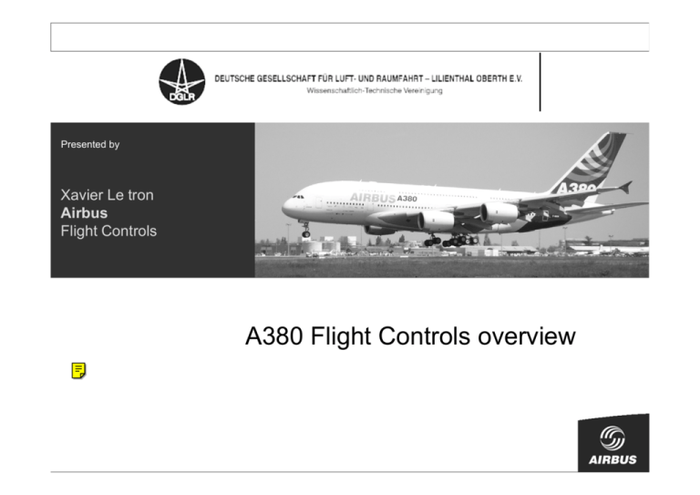
Presented by
Xavier Le tron
Airbus
Flight Controls
A380 Flight Controls overview
A380 Flight Control and Guidance Systems
main novelties
• Aircraft configuration and control surfaces
• Actuator technology
• Power sources for Flight Controls
• Flight Control Architecture and Computers
© AIRBUS S.A.S. All rights reserved. Confidential and proprietary document.
• Back-up controls
• Flight Control Laws
• Conclusion : Flight Tests Findings
27th September 2007
Page 2
Flight Control Surfaces
Trimmable Horizontal
Stabilizer
Slats (6x2)
Droop Nose (2x2)
Flaps (3x2)
Rudders (x2)
Elevators (2x2)
© AIRBUS S.A.S. All rights reserved. Confidential and proprietary document.
spoilers (8x2)
27th September 2007
Ailerons (3x2)
Page 3
Flight Controls: actuator characteristics
stall load
weight
A340/330
13,5 T
21/14,5 T
18 T
22,5 T
85 T
35/65 kg
25/65 kg
40/80 kg
100 kg
380 kg
15,7/10 T
stall load
Ailerons
Spoilers
Elevators
Rudders
© AIRBUS S.A.S. All rights reserved. Confidential and proprietary document.
THSa*
*: loads on trim screw
11/8,6 T
10,2 T
9,4 T
32,5T
27th September 2007
Page 4
A380 Flight Control and Guidance System :
main novelties
• Aircraft configuration and control surfaces
• Actuator technology
• Power sources for Flight Controls
© AIRBUS S.A.S. All rights reserved. Confidential and proprietary document.
• Flight Control Architecture and Computers
• Back-up controls
• Control Laws
27th September 2007
Page 5
Primary Flight Control System Actuators : E(B)HA
Conventional servocontrol
Accumulator
Mode
selector
device
Hydraulic block
Electro-Hydrostatic Actuator
Electrical
(EHA)
Pump Electronics
Servovalve
Hyd.
system
(power)
Ram
Accumulator
Servovalve
replaced by
an electric
motor Pump
Mode
selector
device
system
(power)
Motor
Hydraulic block
Ram
© AIRBUS S.A.S. All rights reserved. Confidential and proprietary document.
EHA in back-up
Servocontrol in
normal
operation
Servovalve
Pump
Accumulator
Mode
selector
device
Hydraulic block
Ram
Electronics
Electrical
system
(power)
Motor
Hydraulic
system
(power)
Electrical Back-up
Hydraulic Actuator
(EBHA)
27th September 2007
Page 6
Primary Flight Controls
equipment status - overview
EHA experience
• 1989: first prototypes EHA/EMA
• 1992 : EBHA aileron first flight on
A320 test aircraft (more than 100 fh)
• 1993/2000: full qualification process,
© AIRBUS S.A.S. All rights reserved. Confidential and proprietary document.
development of large EHA
• 2000/2002: One EHA (inboard aileron)
constantly flight tested on A340 MSN 1
(200 FH, 61 flights), in active and standby modes, start phases, thermal
behaviour...
27th September 2007
Page 7
Example: A380 EHA aileron
© AIRBUS S.A.S. All rights reserved. Confidential and proprietary document.
Electronic module
Hydraulic pump
+ elec. motor
27th September 2007
Page 8
Electro-Hydrostatic Actuator features
• EHA hydraulically autonomous in flight:
• EHA includes a fluid reservoir in order to compensate
thermal dilatation and small external seepage
• EHA fluid reservoir refilling rare, but possible through a
© AIRBUS S.A.S. All rights reserved. Confidential and proprietary document.
connection between each EHA and one centralised circuit
(Filing operation only possible on ground)
27th September 2007
Page 9
THSA DESIGN MAIN FEATURES
End stop
Primary
Nut
Secondary
Nut
Electric
Controller
Gearbox
Hydraulic
Motor
Electric
Motor
© AIRBUS S.A.S. All rights reserved. Confidential and proprietary document.
Upper
Attachment
Hydraulic Valve
Block
Lower
Attachment
Ballscrew
Total length: 2.9 m
27th September 2007
Page 10
THSA DESIGN MAIN FEATURES
A320
A340-600
© AIRBUS S.A.S. All rights reserved. Confidential and proprietary document.
A380
A320
A380
A340-600
27th September 2007
Page 11
A380 Flight Controls: High Lift system
A380 High Lift movables and system mechanical components
(similar concept as A340 Long Range)
Flaps
inner, mid and outer flap
Slats
droop nose
Flap PCU
Slat PCU
© AIRBUS S.A.S. All rights reserved. Confidential and proprietary document.
SFCC
T-gearbox
Wing Tip Brake
Asymmetry Position
Pick-off unit
Flaps Lever
SFCC 2
Motor Control Electronics
Wing Tip Brake
27th September 2007
Page 12
System
A380
Flight
Architecture
Controls: High Lift system
• 2 Drooped Nose Devices per wing (INBD wing) to improve
•
aerodynamic performance (lift to drag ratio)
6 Leading Edge Slats per wing (MIDBD & OUTBD wing)
© AIRBUS S.A.S. All rights reserved. Confidential and proprietary document.
DROOPED NOSE DEVICES :
Supported by hinged arms ; driven
by rotary actuators via link & lever
SLATS :
supported by curved tracks ; driven by
rotary actuators via rack & pinion
27th September 2007
Page 13
High Lift main novelties
• Electric motor for SLAT PCU:
due to 2H/2E concept
Output
Shaft
© AIRBUS S.A.S. All rights reserved. Confidential and proprietary document.
Hydraulic
Motor
DC Electrical
Motor
• Hydraulic Variable Displacement motors: flow consumption
• Fail-Safe Control Lever & Sensor: to improve S/F availability
(no Clean Wing Landing design objective)
27th September 2007
Page 14
A380 Flight Control and Guidance System :
main novelties
• Aircraft configuration and control surfaces
• Actuator technology
• Power sources for Flight Controls
© AIRBUS S.A.S. All rights reserved. Confidential and proprietary document.
• Flight Control Architecture and Computers
• Back-up controls
• Control Laws
27th September 2007
Page 15
A380 Hydraulic and electrical power sources
Electrical System 2:
Generator 4
Generator 3
Power center
Yellow System
Reservoir and main generation components (within pylon)
2 Engine Driven Pumps
1 Ground Electric Motor Pump (within pylon)
2 Engine Driven Pumps
Emergency System:
© AIRBUS S.A.S. All rights reserved. Confidential and proprietary document.
Power center
E.RAT (Flap Track Fairing)
Green System
Electrical System 1:
Power center
Generator 2
Generator 1
1 Ground Electric Motor Pump (within pylon)
2 Engine Driven Pumps
Reservoir and main generation components (within pylon)
2 Engine Driven Pumps
27th September 2007
Page 16
From Blue Hydraulic system to
electro-hydraulic actuators
System 1
System 1
System 2
GEN
1
GEN
2
GEN
3
GEN
4
BUS
BUS
BUS
BUS
BLUE
ELEC
PUMP
BLUE
ELEC
PUMP
BLUE
ELEC
PUMP
Blue hydraulic circuit
replaced by electro-hydraulic
actuators
Blue Electro-Motor Pumps
decentralized within the
actuators
ELEC
PUMP
System 2
GEN
1
GEN
2
GEN
3
GEN
4
BUS
BUS
BUS
BUS
ELEC
PUMP
ELEC
PUMP
ELEC
PUMP
ELEC
PUMP
ELEC
PUMP
© AIRBUS S.A.S. All rights reserved. Confidential and proprietary document.
• Survivability/robustness improvement:
good fuse function
recovery facility in case of power generation failure
good segregation of distribution
dissimilarity on surface actuators power supplying
Redundancy improvement (2 electrical systems replace 1
hydraulic system)
• Reduction of both hydraulic and electrical power
consumption
27th September 2007
Page 17
Electro-hydraulic actuators use
• Performances
EHA
: same performances as adjacent servocontrol,
EBHA
: same performances in hydraulic mode, reduced deflection rate
in electrical mode.
• Electrical mode Activation logics:
In
Normal flight:
– No EHA or EBHA operation (damping & hydraulic mode)
in case of High surface deflection or deflection rate :
– double pressurisation of hydraulic actuators or E(B)HAs
Failure
cases with possible use of EHA and/or EBHA :
© AIRBUS S.A.S. All rights reserved. Confidential and proprietary document.
– Single or double hydraulic failure,
– One engine inoperative,
– Total engine flame-out (with electrical RAT),
– Engine burst
– ...
27th September 2007
Page 18
A380 Flight Control and Hydraulic System :
main novelties
• Aircraft configuration and control surfaces
• Actuator technology
• Power sources for Flight Controls
© AIRBUS S.A.S. All rights reserved. Confidential and proprietary document.
• Flight Control Architecture and Computers
• Back-up controls
• Control Laws
27th September 2007
Page 19
A380 Flight Control System Architecture
• 2H/2E architecture
4
dissimilar power systems to actuate the moving surfaces
Aircraft controllable from one power system
robust architecture (engine rotor burst, structural damages …)
• Electrical RAT supplying EHA and EBHA in case of total engine
flame-out.
© AIRBUS S.A.S. All rights reserved. Confidential and proprietary document.
• No Mechanical Control (Trim Hand Wheel replaced by Switches)
• Improvement of Auto-Pilot availability (computers + Control Unit)
27th September 2007
Page 20
A380 Flight Controls architecture
A380 Primary Flight Control System Architecture – Baseline 1a Revised – October 02
Speed brakes, Ground spoilers
Speed brakes, Ground spoilers
Roll surfaces
Roll surfaces
Slats
AILERONS
O/B
Med
I/B
G Y Y E1 G E2
P2 P3 P3 P1 P1 P2
S3 S1 S1 S2
B
8
7
G
S3
Y
S2
SPOILERS
6
5
4
3
G
E1
P1
Y
P2
E2
G
P3
G
Y
S1
2
1
1
2
G
S2
Y
S3
Y
S3
G
S2
28VDC1ess 28VDC1
Pedals
Feel and
Trim Unit
THSA
S1 S3
G
Y
Flaps
S3
P3
B
S1
P1
G
Y
O/B
© AIRBUS S.A.S. All rights reserved. Confidential and proprietary document.
Electrical Motor.
Conventional hydraulic servocontrol.
EHA, Electro Hydrostatic Actuator.
EBHA, Electrical Backup Hydraulic Actuator.
B
Y
S1
I/B
G E2 G E1
P1 P2 P3 P1
S1 S2 S3 S1
B
G
P3
Y
P2
E2
G
P1
E1
7
8
Y
G
S2 S3
trim
switches
P2
E2
AILERONS
I/B
Med
E2 G
E1 Y
ELEVATORS
I/B
O/B
Upper
Rudder
E1
Lower
Rudder
E1
Y P1 S1 B
G P2 S2
E2
G P1 S1 B
Y P3 S3
E3
E2 Y E1 Y
P2 P3 P1 P2
S2 S3 S1 S2
B
(Colors on E1, E2 and E3 for representation
purposes only, no engineering).
Prim and Sec Flight Control Computers
G
GREEN hydraulic system
E1
E1 AC power (AC1ess side 1)
Command unit : unit
Y
YELLOW hydraulic system
E2
E2 AC power (AC2ess side 2)
E3
E3 AC power (AC1 side 1)
BCM ultimate backup control
A, unit B
Reconfiguration arrow
27th September 2007
O/B
Y G
P2 P1 P1 P3 P3 P2
S2 S1 S1 S3
B
Vertical
Stabilizer
THS
ELEVATORS
P1, P2, P3,
S1, S2, S3
SPOILERS
3
4
5
6
E1
Page 21
Primary Flight Controls: Computers
• 3 PRIMary Flight Control and Guidance Computers
integration
of Auto Flight (ex FGEC) and Flight Control (ex FCPC)
=> 3 Auto-Pilots
• 3 SECondary Flight Control Computers
dissimilar Software and Hardware, simpler Control Laws
• 2 Slats & Flaps Control Computers (SFCC)
• Implementation with IMA:
© AIRBUS S.A.S. All rights reserved. Confidential and proprietary document.
Flight
Controls Data Concentrator
Weight & Balance monitoring
Flight Control Unit back-up
Interface through AFDX:
– Software dataloading,
– Maintenance and warning data,
– Partial inter-system communication
SFCC1
COM MON
SEC1
COM MON
PRIM2
MON
PRIM1
COM MON
Flight COM
Control
PRIM3
COM
SEC2
COM
IOM
S_1_3
SW13
ADIRU1 FM1
ADIRU3
FM2
FM3
ADIRU2
A
EEC3
B
Engines
B
B
A
A
EEC2
MON
S_1_2
IOM
A
EEC1
B
SFCC2
COM
SEC3
MON
COM MON
S_1_1
MON
27th September 2007
Page 22
EEC4
A380 Flight Control and Hydraulic System :
main novelties
• Aircraft configuration and control surfaces
• Actuator technology
• Power sources for Flight Controls
© AIRBUS S.A.S. All rights reserved. Confidential and proprietary document.
• Flight Control Architecture and Computers
• Back-up controls
• Control Laws
27th September 2007
Page 23
Primary Flight controls: Back-up Control
Logical evolution of A320 / A340 / A340-600 family:
Full Fly-By-Wire, with a “Back-up” as an additional precaution to
keep control of the aircraft during temporary loss of:
all Primary Flight Control computers
all Electrical power supply
• A320 : full FBW controls, mechanical Back-up (Pitch Trim & Rudder)
• A340/A330 : like A320, additional Yaw Damper to improve Dutch Roll
damping even in Back-up mode (BYDU with hydraulic micro generator)
© AIRBUS S.A.S. All rights reserved. Confidential and proprietary document.
• A340-600 : like A340 for pitch, Rudder becomes fully Electrical
(BPS + BCM : Back-up Power Supply + Control Module)
• A380 : like A340-600 for Yaw control + BPS+BCM also power
Electrical Pitch Back-Up (elevators) linked to side-stick
Electrical Roll Back-Up (ailerons) linked to side-stick
Pitch Trim (Wheel is replaced by Switches).
27th September 2007
Page 24
Electrical Back-up control
Pitch trim
switches
Side
stick
BPS Yellow
Y
G
Y
Y E1
Y
G
Y
E1
G
E2
Y
Gyro
q,r
G
BPS Green
G
BCM
SPOILERS
G
Side
stick
SPOILERS
Y
Y
G
Y
G
Y
E2
G
E1
Y
G
G E2
AILERONS
Inboard Medium Outboard
E2 G
E1 Y
Y
E1
G
E2
© AIRBUS S.A.S. All rights reserved. Confidential and proprietary document.
G
G
E2
Y
RUDDER
ELEVATORS
Inboard
Inboard
Outboard
G
E2
E1
E1
UPPER
G
THS
ELEVATORS
Outboard
E2
Y
E1
Y
E3
LOWER
Y
27th September 2007
Page 25
Y
G
Electrical Back-up : BPS / BCM
Back-up Power Supply / Back-up Control Module
The BCM consists of :
BPS contains:
© AIRBUS S.A.S. All rights reserved. Confidential and proprietary document.
− A hydraulic motor
− An electrical power generator
− 2 rate gyrometers,
- Analog electronics performing:
- acquisition of pilot controls
- pitch, yaw and roll control law
- actuator control
27th September 2007
Page 26
A380 Flight Control and Hydraulic System :
overview
• Aircraft configuration and control surfaces
• Actuator technology
• Power sources for Flight Controls
© AIRBUS S.A.S. All rights reserved. Confidential and proprietary document.
• Flight Control Architecture and Computers
• Back-up controls
• Control Laws
27th September 2007
Page 27
Flight Controls Laws : main features
Same design philosophy as Airbus FBW:
• Normal Law with auto-trim, Flight Envelope protection
• Alternate Laws with ‘Prot Lost’, but still with auto-trim
• “Direct” law
© AIRBUS S.A.S. All rights reserved. Confidential and proprietary document.
Active Stability Control functions:
•All levels of control laws (Normal, Alternate, “Direct” and even
Back-up) include a Yaw and Pitch damping function
27th September 2007
Page 28
Flight Controls Laws : main features
A380 is the continuation of FBW developed since A320:
¾ normal load factor demand in pitch
¾ roll rate demand in roll, with automatic turn coordination & yaw damping
¾ with flight envelope protections (Stall, attitudes, over-speed)
Main A380 novelties compared to A340 family:
¾ Y* law as lateral normal law: use of Side-Slip probes
© AIRBUS S.A.S. All rights reserved. Confidential and proprietary document.
¾ Load Alleviation functions specific to A380
¾ Use of voters instead of “switches” for protections (AoA, High
Speed, attitudes, …)
¾ Closer integration with Auto-Pilot (same computers)
27th September 2007
Page 29
Conclusion: Flight Test findings
• Generally the aircraft aerodynamics in the flight domain explored (VD &
MD, aft & forward CG, light/heavy) are close to predictions
• Use of E(B)HA:
Checked gradually via Flight Test Instrumentation
“All Electrical Flight” performed (Hydraulic pumps depressurised)
© AIRBUS S.A.S. All rights reserved. Confidential and proprietary document.
These achievements were enabled by early use of simulators (Aircraft –1,
Aircraft 0) and continuous R&D.
A400M, A350 XWB and future Programmes will benefit from these
achievements, plus R&T activities
27th September 2007
Page 30
Conclusion: Future R&T activities
• More Electrical Aircraft:
use
of EMA (Electro-Mechanical Actuators)
Use of High Voltage DC network
• Guidance Navigation & Control:
Ground Automation: Brake-to-Vacate, Airport Navigation & Auto-Pilot…
Multi-Objective design (handling qualities, comfort, loads, fatigue, …)
ATM 4D including specific approach patterns
© AIRBUS S.A.S. All rights reserved. Confidential and proprietary document.
27th September 2007
Page 31
© AIRBUS S.A.S. All rights reserved. Confidential and proprietary document.
Thank you for your attention
27th September 2007
Page 32
This document and all information contained herein is the sole
property of AIRBUS S.A.S. No intellectual property rights are
granted by the delivery of this document or the disclosure of
its content. This document shall not be reproduced or
disclosed to a third party without the express written consent
of AIRBUS S.A.S. This document and its content shall not be
used for any purpose other than that for which it is supplied.
© AIRBUS S.A.S. All rights reserved. Confidential and proprietary document.
The statements made herein do not constitute an offer. They
are based on the mentioned assumptions and are expressed
in good faith. Where the supporting grounds for these
statements are not shown, AIRBUS S.A.S. will be pleased to
explain the basis thereof.
27th September 2007
Page 33


