CMPS 10 Winter 2011- Homework Assignment 5
advertisement
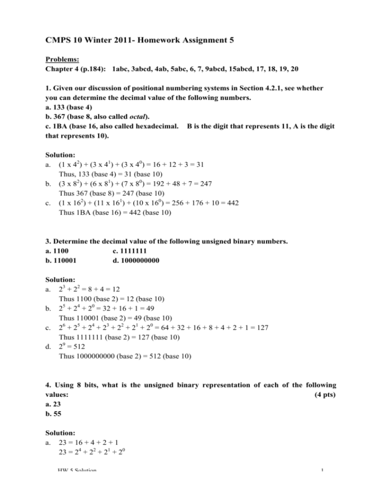
CMPS 10 Winter 2011- Homework Assignment 5 Problems: Chapter 4 (p.184): 1abc, 3abcd, 4ab, 5abc, 6, 7, 9abcd, 15abcd, 17, 18, 19, 20 1. Given our discussion of positional numbering systems in Section 4.2.1, see whether you can determine the decimal value of the following numbers. a. 133 (base 4) b. 367 (base 8, also called octal). c. 1BA (base 16, also called hexadecimal. B is the digit that represents 11, A is the digit that represents 10). Solution: a. (1 x 42) + (3 x 41) + (3 x 40) = 16 + 12 + 3 = 31 Thus, 133 (base 4) = 31 (base 10) b. (3 x 82) + (6 x 81) + (7 x 80) = 192 + 48 + 7 = 247 Thus 367 (base 8) = 247 (base 10) c. (1 x 162) + (11 x 161) + (10 x 160) = 256 + 176 + 10 = 442 Thus 1BA (base 16) = 442 (base 10) 3. Determine the decimal value of the following unsigned binary numbers. a. 1100 c. 1111111 b. 110001 d. 1000000000 Solution: a. 23 + 22 = 8 + 4 = 12 Thus 1100 (base 2) = 12 (base 10) b. 25 + 24 + 20 = 32 + 16 + 1 = 49 Thus 110001 (base 2) = 49 (base 10) c. 26 + 25 + 24 + 23 + 22 + 21 + 20 = 64 + 32 + 16 + 8 + 4 + 2 + 1 = 127 Thus 1111111 (base 2) = 127 (base 10) d. 29 = 512 Thus 1000000000 (base 2) = 512 (base 10) 4. Using 8 bits, what is the unsigned binary representation of each of the following values: (4 pts) a. 23 b. 55 Solution: a. 23 = 16 + 4 + 2 + 1 23 = 24 + 22 + 21 + 20 HW 5 Solution 1 b. Thus 23 (base 10) = 10111 (base 2) 55 = 32 + 16 + 4 + 2 + 1 55 = 25 + 24 + 22 + 21 + 20 Thus 55 (base 10) = 110111 5. Assume that the following 10-bit numbers represent signed integers using sign/magnitude notation. The sign is the leftmost bit and the remaining 9 bits represent the magnitude. What is the decimal value of each? (6 pts) a. 1000110001 c. 1000000001 b. 0110011000 Solution: a. -(25 + 24 + 20) = -(32 + 16 + 1) = -49 Thus 1000110001 (base 2) = -49 (base 10) b. 28 + 27 + 24 + 23 = 256 + 128 + 16 + 8 = 408 Thus 0110011000 (base 2) = 408 (base 10) c. -(20) = -1 Thus 1000000001 (base 2) = -1 (base 10) 6. Assume we use 10 bits to represent signed integers using sign/magnitude notation. What are the largest (in absolute value) positive and negative numbers that can be represented on our system? Solution: The largest positive integer is 0111111111 (base 2), which is 511 (base 10). The smallest negative integer is 1111111111 (base 2), which is -511 (base 10). 7. Show the step-by-step addition of the following two 10-bit unsigned binary values, including showing the carry bit to each successive column. Solution: 111 111 0011100011 (decimal 227) +0001101110 (decimal 110) 0101010001 (decimal 337) 9. Using the ASCII code set given in Figure 4.3, s how the internal binary representation for the following character strings. a. AbC c. $25.00 b. Mike d. (a+b) HW 5 Solution 2 Solution: To answer this problem, we simply look up the appropriate values in Figure 4.3 (page 141). Spaces are used to break up the individual characters below. a. b. c. d. 01000001 01100010 01000011 01001101 01101001 01101011 01100101 00100100 00110010 00110101 00101110 00110000 00110000 00101000 01100001 00101011 01100010 00101001 15. Assume that a = 1, b = 2, and c = 2. Boolean expressions? a. (a > 1) OR (b = c) b. [(a + b) > c] AND (b c) c. NOT (a = 1) d. NOT [(a = b) OR (b = c)] What is the value of each of the following (8 pts) Solution: a. a is not greater than 1, but b does equal c. Therefore, we get: false OR true, which evaluates to: True. b. a + b is greater than c, and b is less than or equal to c. Therefore, we get: true AND true, which evaluates to: True. c. a is equal to 1. Therefore, we get: NOT(true), which evaluates to: False. d. a does not equal b, and b = c. Therefore, we get: NOT(false OR true), which evaluates to: False. 17. Using the circuit construction algorithm of Section 4.4.2, design a circuit using only AND, OR, and NOT gates to implement the following truth table. (2 pts) a b Output 0 0 1 0 1 1 1 0 1 1 1 0 This operation is termed NAND, for Not AND, and it can be constructed as a single gate as shown in Figure 4.17(a). Solution: We construct the Boolean expression: HW 5 Solution 3 Using this expression, we can construct the following circuit diagram: Note that there are several variations on this answer – in particular, the last two OR gates can be moved around. One OR gate must connect two AND gates (any two), and the other OR gate must connect the first OR gate and the last AND gate. 18. Using the circuit construction algorithm of Section 4.4.2, design a circuit using only AND, ORR, and NOT gates to implement the following truth table. a b Output 0 0 1 0 1 1 1 0 0 1 1 1 This operation is termed logical implication, and it is an important operator in symbolic logic. Solution: We construct the Boolean expression: Using this expression, we can construct the following circuit diagram: This solution follows the same guidelines as the last answer – the OR gates can be moved around in any order with the AND gates (following the rules from above). 19. Build a majority-rules circuit. This is a circuit that has three inputs and one output. The value of its output is 1 if and only if two or more of its inputs are 1; otherwise the output of the circuit is 0. For example, if the three inputs are 0, 1, 1, your circuit should output a 1. If its three inputs are 0, 1, 0, it should output a 0. This circuit is HW 5 Solution 4 frequently used in fault-tolerant computing – environments where a computer must keep working correctly no matter what, for example as on a deep-space vehicle where making repairs is impossible. In these conditions, we might choose to put three computers on board and have all three do every computation; if two ore more of the systems produce the same answer, we accept it. Thus, one of the machines could fail and the system would still work properly. Solution: First we must construct a truth table to work from. Using the description above, we can generate the following truth table: a b c Output 0 0 0 0 0 0 1 0 0 1 0 0 0 1 1 1 1 0 0 0 1 0 1 1 1 1 0 1 1 1 1 1 From this truth table, we can now construct a Boolean expression: Using this expression, we can then create the following circuit diagram: This circuit diagram can be modified to place any two AND gates with one OR gate, and the other two AND gates with the other OR gate. The final OR gate must take input from the other two OR gates. 20. Design an odd-parity circuit. This is a circuit that has three inputs and one output. The circuit outputs a 1 if and only if an even number (0 or 2) of its inputs are a 1. Otherwise, the circuit outputs a 0. Thus the sum of the number of 1 bits in the input HW 5 Solution 5 and the output is always an odd number. (This circuit is used in error checking. By adding up the number of 1 bits, we can determine whether any single input bit was accidentally changed. If it was, the total number of 1s is an even number when we know it should be an odd value). (2 pts) Solution: First we must construct a truth table to work from. the following truth table: Using the rules above, we can generate a b c Output 0 0 0 1 0 0 1 0 0 1 0 0 0 1 1 1 1 0 0 0 1 0 1 1 1 1 0 1 1 1 1 0 From this truth table, we can now construct a Boolean expression: Using this expression, we can then create the following circuit diagram: Like the last problem, this circuit diagram can be modified to place any two AND gates with one OR gate, and the other two AND gates with the other OR gate. The final OR gate must take input from the other two OR gates. HW 5 Solution 6


