Experiment 19
advertisement
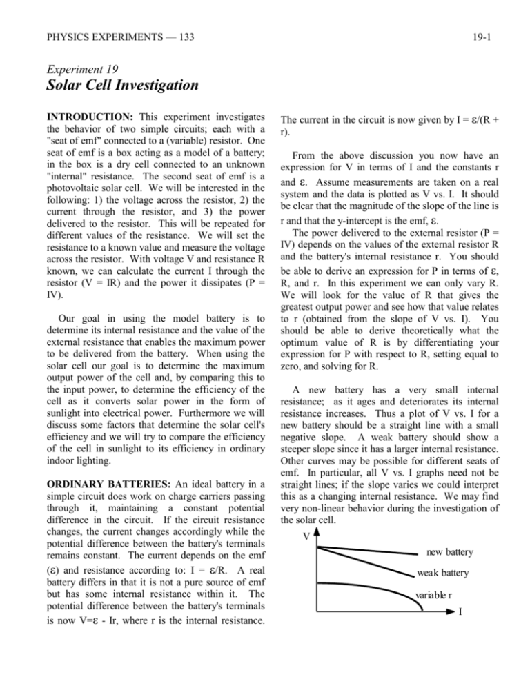
PHYSICS EXPERIMENTS — 133 19-1 Experiment 19 Solar Cell Investigation INTRODUCTION: This experiment investigates the behavior of two simple circuits; each with a "seat of emf" connected to a (variable) resistor. One seat of emf is a box acting as a model of a battery; in the box is a dry cell connected to an unknown "internal" resistance. The second seat of emf is a photovoltaic solar cell. We will be interested in the following: 1) the voltage across the resistor, 2) the current through the resistor, and 3) the power delivered to the resistor. This will be repeated for different values of the resistance. We will set the resistance to a known value and measure the voltage across the resistor. With voltage V and resistance R known, we can calculate the current I through the resistor (V = IR) and the power it dissipates (P = IV). Our goal in using the model battery is to determine its internal resistance and the value of the external resistance that enables the maximum power to be delivered from the battery. When using the solar cell our goal is to determine the maximum output power of the cell and, by comparing this to the input power, to determine the efficiency of the cell as it converts solar power in the form of sunlight into electrical power. Furthermore we will discuss some factors that determine the solar cell's efficiency and we will try to compare the efficiency of the cell in sunlight to its efficiency in ordinary indoor lighting. ORDINARY BATTERIES: An ideal battery in a simple circuit does work on charge carriers passing through it, maintaining a constant potential difference in the circuit. If the circuit resistance changes, the current changes accordingly while the potential difference between the battery's terminals remains constant. The current depends on the emf () and resistance according to: I = /R. A real battery differs in that it is not a pure source of emf but has some internal resistance within it. The potential difference between the battery's terminals is now V= - Ir, where r is the internal resistance. The current in the circuit is now given by I = /(R + r). From the above discussion you now have an expression for V in terms of I and the constants r and . Assume measurements are taken on a real system and the data is plotted as V vs. I. It should be clear that the magnitude of the slope of the line is r and that the y-intercept is the emf, . The power delivered to the external resistor (P = IV) depends on the values of the external resistor R and the battery's internal resistance r. You should be able to derive an expression for P in terms of , R, and r. In this experiment we can only vary R. We will look for the value of R that gives the greatest output power and see how that value relates to r (obtained from the slope of V vs. I). You should be able to derive theoretically what the optimum value of R is by differentiating your expression for P with respect to R, setting equal to zero, and solving for R. A new battery has a very small internal resistance; as it ages and deteriorates its internal resistance increases. Thus a plot of V vs. I for a new battery should be a straight line with a small negative slope. A weak battery should show a steeper slope since it has a larger internal resistance. Other curves may be possible for different seats of emf. In particular, all V vs. I graphs need not be straight lines; if the slope varies we could interpret this as a changing internal resistance. We may find very non-linear behavior during the investigation of the solar cell. V new battery weak battery variable r I 19-2 RADIATION AND SOLAR CELLS: It is beyond the scope of this class to go into the details of photocells. Briefly, the photocells we are using are made of a very thin layer of "n-type" (or "p-type") semiconductor silicon that has been deposited on a p-type (or n-type) silicon base. Each of these "types" is normally electrically neutral but the n-type contains loosely bound electrons (which are negative and hence the name n-type). In p-type materials there are "absences of electrons" which can be considered to be positive "holes". The loosely bound electrons and holes are present in the material because about one in a million of the silicon atoms in the silicon crystal have been replaced by other atomic elements such as arsenic or boron. Electrons and holes diffuse across the p-n junction boundary and set up a positive and negative charge separation region there. This results in a permanent electric field across the p-n junction; the electric field is directed from the n-type material to the p-type. Light can strike the p-n junction. Incoming light photons supply energy and produce free electrons and holes in both the p- and n-type material near the junction. The electrons and holes are then forced by the electric field to move across the junction, giving the n-type material a net negative charge and the ptype material a net positive charge. Output wires connected to the p- and n-type materials will then be charged + and - , just like the terminals of a battery. If the wires are connected across a resistance then charge will flow through the external resistor delivering power to it. The efficiency of a photocell depends on whether or not light is absorbed near the region of the permanent electric field. Thus the absorbing properties of the photocell itself will effect the efficiency of the cell. The temperature of the cell can also effect its efficiency. We will not be able to study these aspects of a photocell's performance. It is beyond the scope of this class to discuss in detail the nature of light. Radiation emitted by a hot object comes off in very small quantized bundles called photons. A photon's energy is inversely proportional to its wavelength. Two things happen PHYSICS EXPERIMENTS — 133 as an object is heated: it emits more photons (becomes brighter) and the photons emitted tend to be at shorter wavelengths (becomes bluer in color). These ideas help explain photocell behavior. Long wavelength photons do not have enough energy to create electron-hole pairs and their energy is converted to heat in the photocell. Short wavelength photons have enough energy to produce an electron-hole pair but their excess energy also goes into heat. The most efficient way to generate electrical energy in a photocell is to shine photons that have just enough energy to produce electron-hole pairs. The wavelength of the minimum energy photon that can create an electron-hole pair in our silicon cell is about 1100 nm. The sun's surface has a temperature of about 5800 K and the wavelength at which the maximum power is emitted is about 500 nm. For a typical incandescent light bulb the corresponding values are 2800 K and 1000 nm. In this experiment we will see if we can determine a difference in cell efficiency under these two lighting conditions. BATTERY EXPERIMENT: You will use the model battery: it is a box with a real battery inside along with an unknown resistor. The real battery provides the emf of our model and the unknown resistor takes the place of the internal resistance, r. 1) Attach the decade box variable resistor R to the model battery. Attach the DC voltmeter across R. Take sufficient data to be able to plot useful V vs. I and P vs. R graphs. The data consists of a measured voltage value V for each R that you select. On your data table you should also have columns for the calculated values of I and P for each point. There is no need to choose the R values uniformly; in fact, it may be preferable to have closely spaced R points near the maximum of the power in the P vs. R graph and more widely spaced R values away from the peak. Roughly determine where the maximum P is while taking data and then concentrate your measurements near the maximum. You will want to be able to accurately locate the maximum and yet have enough data points far from the maximum to give a useful plot. PHYSICS EXPERIMENTS — 133 2) Plot V (vertical) vs. I (horizontal) using an appropriate scale. What do you expect the slope and intercept to be? From the plot of your data determine the internal resistance and the emf of your model battery. Now open the wooden box and using a digital multimeter measure the actual internal resistance (resistor in box) and emf (voltage of the battery). Compare the actual measured values with those obtained from your graph. 3) Plot P vs. R and then determine the value of R that gives the maximum output power. Compare this optimum R with the value you found for the internal resistance, r. How well do your results compare with what is expected from theory? OUTDOOR SOLAR EXPERIMENT: The experiment proceeds just as was done for the model battery, except the photocell will be used instead of the model battery. Connect the cell to the variable resistor with the voltmeter across it. 4) Start outside with bright sunlight incident on the cell. Arrange the cell so that sunlight falls perpendicular to its surface. 5) Take the necessary data to obtain useful V vs. I and P vs. R graphs. Find the optimum resistance that yields the maximum output power from the cell. 6) In order to determine the cell's efficiency you will need to know the amount of solar energy entering the cell. At the top of the atmosphere the accepted value for solar intensity is 1400 watts per square meter. We will use a calibrated meter to determine the solar intensity at our location; the expected value is about 1000 W/m2. This measured solar intensity multiplied by your cell's collection area gives the input power to the cell. (A disassembled cell is on the front table for inspection; the actual collector area of the cell is about 6.0 cm2.) 7) Do the necessary calculations and plot the two required graphs. Determine the maximum output power delivered from the cell to your resistor. 19-3 8) From part (6) you know the input power to your cell. From part (7) you know the maximum output power delivered by your cell. Determine the efficiency of your cell in %. 9) The experiment using the model battery should have shown you that maximum power transfer occurs when R equals r (a condition usually referred to as impedance matching). We will briefly investigate this for the case of the photocell. Look at your V vs. I graph for your cell. Determine the slope of the graph (and thus the internal resistance of the cell) at the point where the maximum power occurs. Compare this experimental value of r with the R at which maximum power is delivered. How do they compare? INDOOR PHOTOCELL EXPERIMENT: 10) Repeat your measurements with your cell indoors. Use an ordinary 100 W electric light bulb placed 20 cm above the cell. (Unfortunately, the bulb's output is not spherically symmetric; for repeatability of results always try to align your bulb with its filament horizontal.) In this case we do not ask you to make complete graphs or take extensive data. Merely take enough data to enable you to find the maximum power delivered to your resistor and the value of R at which this occurs. Again, this is determined from the maximum of your P vs. R data. (Take large resistance steps and then go back and fill in.) 11) Determine the efficiency of your cell. This is slightly more difficult to obtain and below are step by step instructions: a) Obtain the output power from your bulb. Nominally it is the wattage marked on it. Check this value using the power meter on the front table. b) You will need the power per unit area emitted by the bulb at the location of your cell. Assume that the power of the bulb is distributed uniformly over a sphere whose radius equals the distance between the bulb and the cell. To calculate the intensity of the light at the cell's location take the bulb's power (part a) and divide by the surface area of the sphere. 19-4 PHYSICS EXPERIMENTS — 133 surface area =4 r2 r = radius photoce ll c) You need the power entering the cell. This is the product of part (b) times the area of the cell. (A disassembled cell is on the front table for inspection; the actual collector area of the cell is about 6.0 cm2.) d) You have already determined the maximum output power of your cell in part (10), above. e) Find the efficiency of your cell under indoor conditions by taking the ratio of part (d) and part (c). How does the efficiency of your cell compare to its previous value under sunlight conditions? OTHER INDOOR MEASUREMENTS: 12) We ask you to do the indoor measurements again, but under different circumstances. In this case use a lower wattage bulb instead of the 100 W bulb used previously. You knew the intensity of the light at the cell when the 100 W bulb was 20 cm above the cell (part b). Now calculate the distance above the cell where the new light bulb should be placed in order to have the same intensity at the cell. Place the new bulb at that distance from the cell and repeat the experimental work. Remember to keep the bulb's filament horizontal. Determine the cell's efficiency under these circumstances. 13) We ask you to do the indoor measurements yet again using the 100 W bulb, but this time connect the bulb to the "variac". Adjust the variac until the bulb's output power is the same as the lower wattage bulb that was used in part (12) and keep the bulb in the same location as in part (12) with its filament horizontal. What you are doing is lowering the temperature of the 100 W bulb's filament and changing the distribution of photon energies being emitted. Again repeat enough experimental work to enable you to determine the peak power delivered to the bulb and the efficiency of the cell under these circumstances. rev. 8/05
