resistance
advertisement
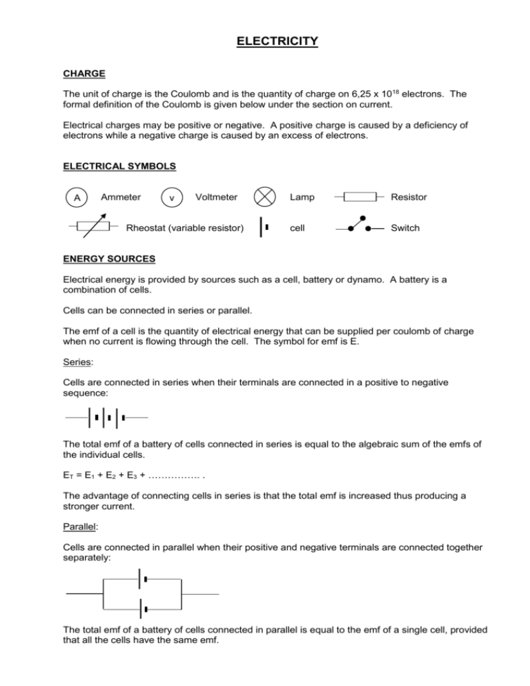
ELECTRICITY CHARGE The unit of charge is the Coulomb and is the quantity of charge on 6,25 x 10¹⁸ electrons. The formal definition of the Coulomb is given below under the section on current. Electrical charges may be positive or negative. A positive charge is caused by a deficiency of electrons while a negative charge is caused by an excess of electrons. ELECTRICAL SYMBOLS A Ammeter v Voltmeter Rheostat (variable resistor) Lamp Resistor cell Switch ENERGY SOURCES Electrical energy is provided by sources such as a cell, battery or dynamo. A battery is a combination of cells. Cells can be connected in series or parallel. The emf of a cell is the quantity of electrical energy that can be supplied per coulomb of charge when no current is flowing through the cell. The symbol for emf is E. Series: Cells are connected in series when their terminals are connected in a positive to negative sequence: The total emf of a battery of cells connected in series is equal to the algebraic sum of the emfs of the individual cells. ET = E1 + E2 + E3 + ……………. . The advantage of connecting cells in series is that the total emf is increased thus producing a stronger current. Parallel: Cells are connected in parallel when their positive and negative terminals are connected together separately: The total emf of a battery of cells connected in parallel is equal to the emf of a single cell, provided that all the cells have the same emf. The advantages of connecting cells in parallel are that the cells last longer and the resistance of the battery in the circuit is decreased thus reducing the internal energy lost. ET = E1 = E2 = E3 = ………. . Examples: Each of the cells has an emf of 2 V. Calculate the emf of the following batteries: 8V 4V 2V 6V SIMPLE CIRCUIT A simple circuit consists of a cell, conducting wires, resistance and switch. POTENTIAL DIFFERENCE The potential difference between two points in a circuit is the energy required to move one coulomb of charge between the points. V W where V = potential difference (V), W = work done (J) and Q = charge (C). Q Example 1: Calculate the potential difference between two points if 20 J of work are required to move a charge of 2 C. V W 20 2V Q 2 Example 2: Calculate the work done in moving a charge of 5 C through a potential difference of 2 V. W = QV = 5 x 2 = 10 J CURRENT An electric current is the flow of charge (positive or negative) from one point to another in an electrical circuit. Conventional current is the flow of positive charge and its direction is from the positive terminal to the negative terminal of a cell. Since a current in a metal is conducted by negative electrons, the electron current flows from negative to positive. However, current direction in metals is always based on the direction that a positive charge would take and is therefore the direction of a conventional current, i.e. from positive to negative. Current strength is the rate at which charge passes a given point in a conductor. The unit of current strength is the ampere (A). (The use of the abbreviation “amp” is incorrect.) I Q where I is the current strength (A), Q = charge (C) and t = time (s). t Example 1: Calculate the current strength when 5 C of charge passes a given point in 2 s. I Q 5 2,5 A t 2 Example 2: Calculate the quantity of charge passing a point in a circuit when a current of 5 A flows for 10 s. Q = It = 5 x 10 = 50 C The formula Q = It can be used to define a Coulomb. A coulomb is the quantity of charge that passes through a conductor when a current of one ampere flows for one second. CONDUCTION IN A METAL In a metal, the atoms are packed closely in a crystal lattice. The outermost electrons of the metal atoms are held loosely and can escape the attractive forces of their nuclei to form positively charged metal ions. These electrons are called free electrons and move around at random. - + - +- +- + -+ +- + - + - + +- + - +- +-+ + -+ - - - + - + + + - + - + -+ -+ If a potential difference is applied across the Mobile electrons Positive atomic ends of the conductor, an electric field is set up residues (ions) in the conductor. Negatively charged electrons are attracted to the positive terminal while the metal ions remain stationary because they are held in a crystal lattice. The movement of electrons is impeded by collisions with the positive metallic ions causing resistance. Every electron that leaves a conductor at the positive terminal is replaced by another from the negative terminal. The overall charge of a conductor is therefore neutral. RESISTANCE The resistance of a conductor is a measure of how much difficulty charges experience in passing through the conductor. A good conductor has a low resistance and a poor conductor has a high resistance. Resistance is caused by collisions between electrons and metal atoms that interfere with the flow of charge. The following factors affect the resistance of a conductor: (1) (2) (3) (4) type of metal used. length of the conductor. thickness (or cross-sectional area). temperature. Resistance is defined as the ratio of potential difference across the ends of a conductor and current strength. R V where R = resistance (), V = potential difference (V) and I = current strength (A). I An ohm is the resistance of a conductor when a potential difference of one volt causes a current of one ampere to flow through it. Example: Calculate the resistance of a conductor when a current of 2 A flows when the potential across its ends is 10 V. R V 10 5 I 2 OHM’S LAW Ohm’s Law states that current strength is directly proportional to the potential difference between the ends of a given resistor provided that temperature remains constant. Mathematical statement: For a given resistor, V I at constant temperature. Mathematical formula: V = IR Experiment to verify Ohm’s Law Set up the apparatus as show in the accompanying diagram. Vary the potential difference across the resistor by moving the rheostat and take five readings of potential difference and current. Precaution: Keep the temperature of the resistor constant. Tabulate your results as follows: 1 2 3 4 5 Potential difference (V) 1,0 2,0 3,0 4,0 5,0 Current (A) 0,5 1,0 1,5 2,0 2,5 V () I 2 2 2 2 2 V A Potential difference (V) Plot a graph of V against I. 5 V = RI + 0 y = mx + C 4 3 The gradient of the graph is equal to R. The y-intercept is at 0. 2 1 0 0 0,5 1,0 1,5 2,0 2,5 I (A) Resistors connected in series Resistors connected in series act as potential dividers. v v1 v1 v2 v3 r1 r2 r3 V = v1 + v2 + v3 IR = Ir1 + Ir2 + Ir3 R = r1 + r2 + r3 (Divide by the common factor I.) The total resistance of a combination of resistors connected in series is equal to the algebraic sum of the component resistors. R = r1 + r2 + r3 + ……. . Example: 2 3 9 R = r1 + r2 + r3 = 2 + 3 + 9 = 14 Since resistors connected in series act as potential dividers, the resistance across any one resistor can be calculated using the formula: r v V. R In the accompanying diagrams, a cell with an emf of 10 V and negligible internal resistance is connected in parallel with a 2 resistor and a rheostat. The resistance of the rheostat is adjusted to illustrate how the potential difference across resistors can be varied. 10 V 10 V 0 0 8 3 2 V1 2 V2 V1 V2 The resistance of the rheostat is increased from 3 in Diagram 1 to 8 in Diagram 2 causing a different division in potential difference across the resistors. I R = r1 + r2 = 2 + 3 = 5 V 10 2A R 5 R = r1 + r2 I V 10 1A R 10 = 2 + 8 = 10 V1 = IR = 2 x 2 = 4 V V2 = IR = 2 x 3 = 6 V V1 = IR = 1 x 2 = 2 V V2 = IR = 1 x 8 = 8 V OR v r 2 r 3 V 10 4V v V 10 6 V R 5 R 5 v r 2 V 10 2 V R 10 v r 8 V 10 8 V R 10 The above calculations show how the division of potential difference increases across the rheostat as the resistance is increased Resistors connected in parallel Resistors connected in parallel act as current dividers. i1 I i2 i3 I = i1 + i2 + i3 r1 r2 I r3 V V V V 1 1 1 1 (Divide by the common factor, V.) R r1 r 2 r 3 R r1 r 2 r 3 The reciprocal of the total resistance is equal to the sum of the reciprocals of the resistances of the component resistors. Example: 6 3 1 1 1 1 1 1 1 1 2 6 9 R 0,67 R r1 r 2 r 3 6 3 1 6 6 1 Consider the following combination of resistors connected in parallel that act as current dividers. 3A 1 2 The current flowing through resistors connected in parallel will be inversely proportional to their resistances, i.e. the greater the resistance the smaller the current. The ratio of the resistances is 2 : 1 (total 3). Two-thirds of the current will therefore flow down one resistor and the remaining one-third down the other resistor. The larger current will flow down the resistor having the smaller resistance. 2 3 2A 3 1 3 1A 3 1 resistor: 2 resistor: METERS An ammeter measures the strength of an electric current. It has a low resistance and is connected in series in a circuit. A voltmeter measures the potential difference between two points in a circuit. It has a high resistance and is connected in parallel across the two points. POWER Power is the rate at which work is done. P W where P = power in watts (W), W = work in joules (J) and t = time (s). t Example 1: Calculate the power when 100 J of electrical energy is used in 2 seconds. P W 100 50 W t 2 Example 2: Calculate the electrical energy used when a 100 W electric bulb burns for 2 minutes. W = Pt = 100 x 2 x 60 = 12 000 J Other formulae for power and work: W = QV = VIt P (Substituting the formulae W = QV and Q = It) W VIt VI t t P VI V V V2 R R P = VI = IR x I = I2R W = Pt = I2Rt 2 W = Pt = V t R (Substituting I V ) R (Substituting V = IR) LOST VOLTS EFFECT The emf of a cell is the energy per coulomb available across the terminals of a cell when no current flows. Since a cell has resistance, energy is used to overcome the internal resistance when a current flows. This results in a decrease in potential difference across the terminals because less energy per coulomb is available to drive a current around the external circuit. The decrease in potential difference is called the lost volts effect. Emf = potential difference + energy used per coulomb to overcome internal resistance. E = V + Ir where E is the emf (V), V the potential difference (V), I the current (A) and r the internal resistance (). OR V = E – Ir CIRCUIT DIAGRAM Example: V1 In the accompanying circuit diagram, each cell has an emf of 2 V and internal resistance of 0,5 . 1. Calculate the readings on A, V1 and V2 when the switch is open. 2. 2.1 2.2 2.3 2.4 2.5 Calculate the following when switch S is closed: the total resistance of the circuit. the reading on A the reading on V2 the charge passing through A in 2 minutes. the power used by the 0,5 resistor. 1. V1 = 5 x 2 = 10 V 2.1 Resistance of cells in series: R = r1 + r2 + r3 + r4 + r5 = 5 x 0,5 = 2,5 Resistance of resistors in parallel: 1 1 1 1 1 1 2 3 R 2 R r1 r 2 6 3 6 6 Total resistance of circuit: R = r1 + r2 + r3 = 2,5 + 2 + 0,5 = 5 A 6 V2 3 S 0,5 V2 = 0 V and A = 0 A V 10 2A R 5 2.2 A: I 2.3 V2: V = IR = 2 x 2 = 4 V 2.4 Q = It = 2 x 2 x 60 = 240 C 2.5 P = I2R = 22 x 0,5 = 2 W. (The resistance between the points to which the voltmeter is connected is equivalent to the resistance of the parallel combination of resistors. The total current flowing through the two resistors is 2 A.)


