Arithmetic Circuits – Addition, Subtraction, & Multiplication The
advertisement
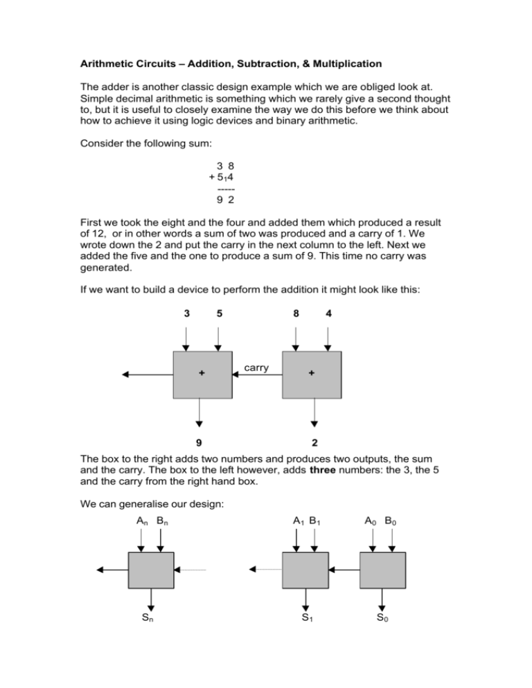
Arithmetic Circuits – Addition, Subtraction, & Multiplication The adder is another classic design example which we are obliged look at. Simple decimal arithmetic is something which we rarely give a second thought to, but it is useful to closely examine the way we do this before we think about how to achieve it using logic devices and binary arithmetic. Consider the following sum: 3 8 + 514 ----9 2 First we took the eight and the four and added them which produced a result of 12, or in other words a sum of two was produced and a carry of 1. We wrote down the 2 and put the carry in the next column to the left. Next we added the five and the one to produce a sum of 9. This time no carry was generated. If we want to build a device to perform the addition it might look like this: 3 5 + 9 8 carry 4 + 2 The box to the right adds two numbers and produces two outputs, the sum and the carry. The box to the left however, adds three numbers: the 3, the 5 and the carry from the right hand box. We can generalise our design: An Bn Sn A1 B1 A0 B0 S1 S0 Performing the addition in binary is much the same but a little more tedious. 1001 10 + 1 1 0 1111 0 --------------10111 00 (38 in decimal) (54 in decimal) (92 in decimal) If we now move on to consider what happens inside these black boxes it should be apparent that the box on the right is simpler than the others because it only ever adds two numbers. For reasons which (might!) become clear later we call this box a ‘half adder’ and the others we call ‘full adders’. As usual we can express the requirements in a truth table. Our half adder has two inputs: A and B, and two outputs: S and C (really we have two truth tables in one). A B S C 0 0 0 0 0 1 1 0 1 0 1 0 1 1 0 1 Hopefully you have spotted that S is merely an EX-OR operation and C is a AND operation, so our half adder is simply: A B S C With a little thought we can figure out how to build a full adder from two half adders (hence the names). Remember that the full adder is adding three bits, let’s call these X, Y, and Z, so the sum we need is S = X+Y+Z. It doesn’t matter what order we add them in as X+Y+Z = (X+Y)+Z = X+(Y+Z), so let’s take X and Y and add them first to produce an intermediate sum, R. X+Y=R We only have two bits (X and Y) so we can do this with a half adder and our final result will be given by: S=R+Z We can do this with a half adder too, so we’re almost home and dry. Our full adder is beginning to take shape: Z X Y S R Ca Cb We still have to deal with the carries. Our immediate thought might be to add them both together using another EX-OR gate. This will certainly work but it isn’t the simplest solution, nor is it one you will ever see in any textbook! Think carefully about the difference between an Exclusive OR gate and a normal (Inclusive) OR gate. The only difference occurs when both inputs are 1 , the OR has an output of 1 and the EX-OR an output of 0. Returning to our half finished full adder, on close examination it turns out that the two carries, Ca and Cb in the diagram, can never both be 1, so it makes no difference whether we use an OR or an EX-OR! OR gates are simpler than EX-OR gates so it makes sense to use the easiest option and our completed full adder is: Cin A B S Cout Unfortunately this is a somewhat contrived example, in reality we wouldn’t build full adders we’d buy a chip containing several of them, however it is useful to understand how they work. Subtraction We could repeat this exercise for subtractor circuits but there isn’t much point. We already have a technique whereby we can use the adder to perform subtraction. Suppose you want to subtract B from A (A-B), this is exactly the same as saying A+(-B). In other words, if we have a way of representing ‘minus B’ then all we need to do is add this to A to produce a result. We already have such a representation in the twos complement scheme we looked at earlier. To negate a number all we need to do is invert it and add 1. A – B = A + (-B) = A+ /B + 1 This is easy to achieve using the adder. We can invert B using inverters and if we use a full adder instead of a half adder we can add one by using the carryin of the first stage. With a little ingenuity we can use the same circuit to perform addition and subtraction. The diagram illustrates a four bit adder/subtractor designed around a four bit adder. The EX-OR gates will invert B if the switch is set to 1 or do nothing if it is set to 0, check the truth table for EX-OR to confirm this. Multiplication and Division It would be nice if we could design similar circuits for multiplication and division, however it isn’t easy to design such circuits and they tend to be very complex and expensive. In actual fact, most microprocessors do not even have multiplier circuits, they cheat! It is very easy to multiply a decimal number by 10 or a binary number by 2. If we multiply a decimal number by 10 we simply add a zero to the right hand side eg 28 x 10 = 280. Similarly, adding a zero to the right hand side of a binary number is equivalent to multiplying the number by 2. Adding a zero to the right hand side of a hexadecimal number is equivalent to multiplying by 16 etc. etc. Consider the binary number Add an extra zero: 1011 (eleven in decimal) 10110 (twenty two in decimal) A more general way of thinking about this, particularly if fractions are involved is ‘shifting the point’. Each time we shift the decimal point to the right we multiply the number by 10, or if we shift it to the left we divide by 10. Because of the way binary numbers are stored in the logic circuits of computers it actually makes a lot more sense to shift the number rather than the (binary) point. Consider the following example: 128 64 32 16 8 4 2 1 0 0 0 0 0 1 1 0 1 1 1 1 1 1 0 0 1 1 1 0 1 1 1 0 ------ a ------ b ------ c Beginning with a (59 decimal) we shift one position to the right to obtain b (29 decimal), and one place to the left to obtain c (118 decimal). There is a slight complication if negative numbers are involved; in this example a zero was shifted in on the left hand side of b, and a one was lost from the right hand side. Suppose our starting number was 10000000 (-128 in twos complement notation). If we applied the same procedure we’d get 01000000 (+64) by shifting it right one place. If we’d shifted a one into the left hand side we would have 11000000 (-64) which is the correct answer. The solution to our problem is to shift a zero in when the number is positive (the msb is zero) and a one when it’s negative (the msb is one). You will encounter this later when we look at microprocessors in more detail. Now we can think about multiplying by any number, rather than just ‘two’. Once again it is useful to think about decimal arithmetic; let’s suppose we want to multiply the two decimal numbers 425 and 218. Nowadays most of us would simply reach for an electronic calculator to do this and remembering how to do it without one might be a challenge! 425 218 --------85000 4250 3400 --------92650 ------ 1 ------ 2 ------ 3 In step 1 we began by writing two zeroes and then multiplied 425 by 2. In step 2 we wrote one zero and multiplied 425 by 1. In step 3 we multiplied 425 by 8. Finally, adding the three numbers together produced our result: 92650 Let’s do this again, but this time, instead of 218 we’ll use 101 (one hundred and one) as the multiplier. 425 101 --------42500 ------ 1 0000 ------ 2 425 ------ 3 --------42925 Spot the difference? This time it was a lot easier because our multiplier only contains 1s and 0s. In step 1 we wrote down the two zeroes and then multiplied 425 by 1. Of course there is nothing tricky about multiplying any number by 1! In step 2 we multiplied 425 by 0 which is fairly trivial too! Let’s try once more, this time we’ll replace the 425 by 111 (one hundred and eleven) 111 101 --------11100 ------ 1 0000 ------ 2 111 ------ 3 --------11211 There shouldn’t be any surprises so far. What if 111 and 101 were actually binary numbers (7 and 5 respectively in decimal)? Steps 1,2, and 3 will be exactly the same! We just have to remember we’re working in binary when we add everything together: 111 101 --------11100 0000 111 --------100011 ------ 1 ------ 2 ------ 3 The result 100011 is what we’d expect (7 x 5 = 35) and we’ve succeeded in multiplying our numbers without really doing any multiplication at all! All that we’ve done is shifted the 111 two places to the left in step 1. Done nothing in step 2, then written down 111 in step 3, and finished off by adding everything up. This is an extremely common method of performing multiplication. So common in fact, that it has its own, rather unimaginative name, ‘the shift and add algorithm’! If you’re wondering how on earth you would draw Karnaugh maps to describe this operation and build a circuit then don’t worry. You can’t. This algorithm is sequential, there are several steps involved in producing an answer and the logic design methods that we’ve looked at so far simply can’t do this. Microprocessors are very good at this kind of thing and even very simple devices often have ‘Multiply’ instructions. Usually, when such an instruction is executed, a lot of shifting and adding happens behind the scenes. Division is another story, although it is somewhat similar. Just as we can live without dedicated circuits to perform multiplication, we can get by without divider circuits too. We won’t explore division here but you might not be too surprised that a ‘shift and subtract’ algorithm is usually used. Lateral Thinking Is the method outlined above, the only way in which we can multiply two numbers together? Perhaps in your primary school days you used ‘table cards’? A table card is a very simple device for avoiding arithmetic (although they are usually intended to encourage mental arithmetic!) Consider the table below: 1 2 3 4 5 6 7 8 9 10 11 12 1 1 2 3 4 5 6 7 8 9 10 11 12 2 2 4 6 8 10 12 14 16 18 20 22 24 3 4 3 4 6 8 9 12 12 16 15 20 18 24 21 28 24 32 27 36 30 40 33 44 36 48 5 5 10 15 20 25 30 35 40 45 50 55 60 6 7 6 7 12 14 18 21 24 28 30 35 36 42 42 49 48 56 54 63 60 70 66 77 72 84 8 8 16 24 32 40 48 56 64 72 80 88 96 9 10 9 10 18 20 27 30 36 40 45 50 54 60 63 70 72 80 81 90 90 100 99 110 108 120 11 11 22 33 44 55 66 77 88 99 110 121 132 12 12 24 36 48 60 72 84 96 108 120 132 Using this table we can perform multiplication by simply ‘looking up’ the answer. For example, in the table above we can see that the product of 7 and 9 is 63. 144 Could we use such a device in a computer using a ‘lookup table’ in the computer’s memory? When we multiply two numbers we call one of them the ‘multiplier’ and the other the ‘multiplicand’. Suppose that our multiplier and multiplicand are both 8-bit integers, this means that the product may be a 16bit integer. It also means that our table will be big; 256 rows and 256 columns (including zero). This means that the table will require 65,536 16-bit words (128 kilobytes!) of storage. That’s a lot of memory for a 8-bit multiplication! There is a way around this. Consider the following: (a + b)2 = a 2 + b2 + 2ab (a – b) 2 = a2 + b2 - 2ab ---------- (1) ---------- (2) Subtract (2) from (1): (a + b)2 - (a – b) 2 = 4ab Rearranging this: ab = (a + b)2 - (a – b) 2 4 So we can multiply two numbers by finding their sum and differences. Squaring these. Subtract one from the other, and then dividing the result by four. At first this seems like a perfectly idiotic way of doing things but let’s check that it does actually work: Let a=9 and b=7 to match the example above. 9x7 = (9 + 7 )2 – (9 – 7) 2 4 9x7 = 162 – 2 2 4 9x7 = 252 4 9x7 = 63 It works! How does this help us? We can now use a lookup technique in this approach because only a table of squares is required. Following on from the example above, our table will be much smaller and look like: n 1 2 3 4 5 6 7 8 9 10 11 12 13 14 15 16 17 18 19 20 21 22 23 24 25 n2 1 4 9 16 25 36 49 64 81 100 121 144 169 196 225 196 289 324 361 400 441 484 529 576 625 So, in our example, to ‘calculate’ 9x7 we find the sum and difference; 16 & 2 Now look up their squares; 196 & 4. Then 196 – 4 = 192. Divide 192 by 4 to give the result of 63 (we could have missed this stage by using a table which is already divided by 4). However crazy this might seem, it can be significantly faster than a ‘shift and add’ algorithm.

