we perform the projection of the subwavelength Bloch TEM modes
advertisement

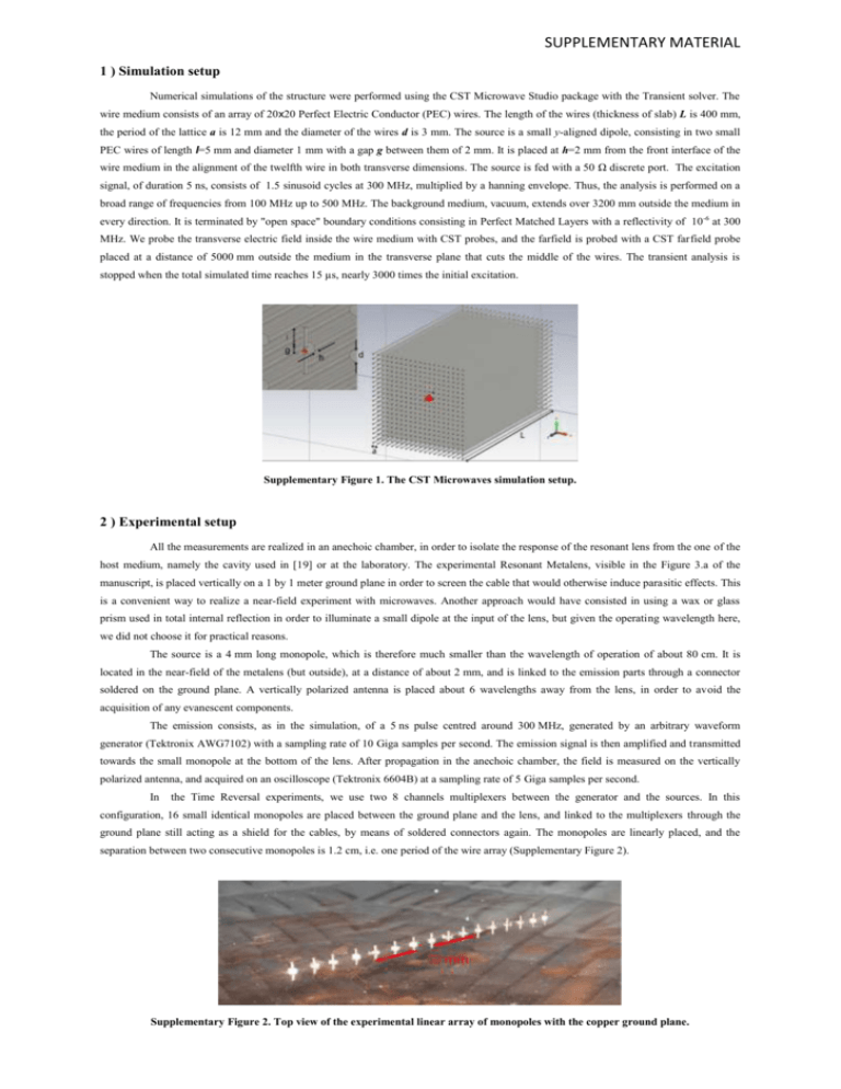
SUPPLEMENTARY MATERIAL 1 ) Simulation setup Numerical simulations of the structure were performed using the CST Microwave Studio package with the Transient solver. The wire medium consists of an array of 20x20 Perfect Electric Conductor (PEC) wires. The length of the wires (thickness of slab) L is 400 mm, the period of the lattice a is 12 mm and the diameter of the wires d is 3 mm. The source is a small y-aligned dipole, consisting in two small PEC wires of length l=5 mm and diameter 1 mm with a gap g between them of 2 mm. It is placed at h=2 mm from the front interface of the wire medium in the alignment of the twelfth wire in both transverse dimensions. The source is fed with a 50 Ω discrete port. The excitation signal, of duration 5 ns, consists of 1.5 sinusoid cycles at 300 MHz, multiplied by a hanning envelope. Thus, the analysis is performed on a broad range of frequencies from 100 MHz up to 500 MHz. The background medium, vacuum, extends over 3200 mm outside the medium in every direction. It is terminated by "open space" boundary conditions consisting in Perfect Matched Layers with a reflectivity of 10 -6 at 300 MHz. We probe the transverse electric field inside the wire medium with CST probes, and the farfield is probed with a CST farfield probe placed at a distance of 5000 mm outside the medium in the transverse plane that cuts the middle of the wires. The transient analysis is stopped when the total simulated time reaches 15 µs, nearly 3000 times the initial excitation. Supplementary Figure 1. The CST Microwaves simulation setup. 2 ) Experimental setup All the measurements are realized in an anechoic chamber, in order to isolate the response of the resonant lens from the one of the host medium, namely the cavity used in [19] or at the laboratory. The experimental Resonant Metalens, visible in the Figure 3.a of the manuscript, is placed vertically on a 1 by 1 meter ground plane in order to screen the cable that would otherwise induce parasitic effects. This is a convenient way to realize a near-field experiment with microwaves. Another approach would have consisted in using a wax or glass prism used in total internal reflection in order to illuminate a small dipole at the input of the lens, but given the operating wavelength here, we did not choose it for practical reasons. The source is a 4 mm long monopole, which is therefore much smaller than the wavelength of operation of about 80 cm. It is located in the near-field of the metalens (but outside), at a distance of about 2 mm, and is linked to the emission parts through a connector soldered on the ground plane. A vertically polarized antenna is placed about 6 wavelengths away from the lens, in order to avoid the acquisition of any evanescent components. The emission consists, as in the simulation, of a 5 ns pulse centred around 300 MHz, generated by an arbitrary waveform generator (Tektronix AWG7102) with a sampling rate of 10 Giga samples per second. The emission signal is then amplified and transmitted towards the small monopole at the bottom of the lens. After propagation in the anechoic chamber, the field is measured on the vertically polarized antenna, and acquired on an oscilloscope (Tektronix 6604B) at a sampling rate of 5 Giga samples per second. In the Time Reversal experiments, we use two 8 channels multiplexers between the generator and the sources. In this configuration, 16 small identical monopoles are placed between the ground plane and the lens, and linked to the multiplexers through the ground plane still acting as a shield for the cables, by means of soldered connectors again. The monopoles are linearly placed, and the separation between two consecutive monopoles is 1.2 cm, i.e. one period of the wire array (Supplementary Figure 2). Supplementary Figure 2. Top view of the experimental linear array of monopoles with the copper ground plane.


