doc - Mirus International Inc.
advertisement
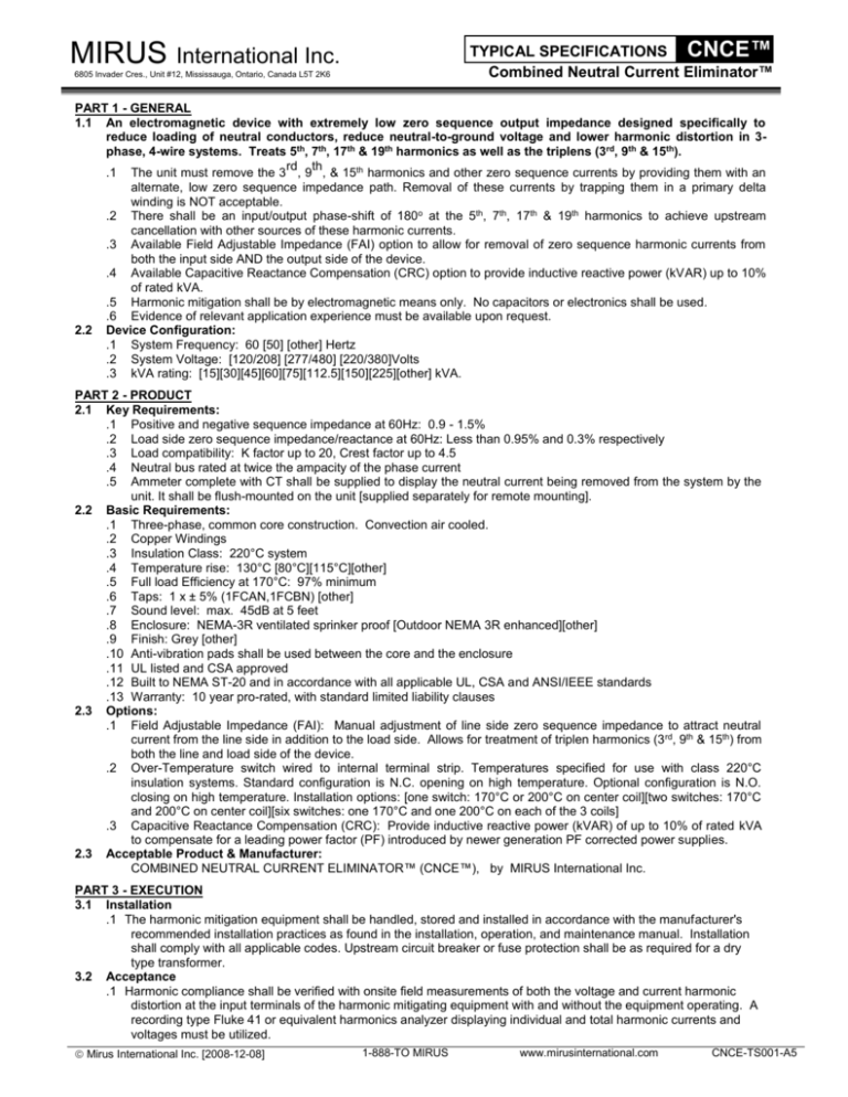
TYPICAL SPECIFICATIONS CNCE™ Combined Neutral Current Eliminator™ MIRUS International Inc. 6805 Invader Cres., Unit #12, Mississauga, Ontario, Canada L5T 2K6 PART 1 - GENERAL 1.1 An electromagnetic device with extremely low zero sequence output impedance designed specifically to reduce loading of neutral conductors, reduce neutral-to-ground voltage and lower harmonic distortion in 3phase, 4-wire systems. Treats 5th, 7th, 17th & 19th harmonics as well as the triplens (3rd, 9th & 15th). rd th .1 The unit must remove the 3 , 9 , & 15th harmonics and other zero sequence currents by providing them with an alternate, low zero sequence impedance path. Removal of these currents by trapping them in a primary delta winding is NOT acceptable. .2 There shall be an input/output phase-shift of 180o at the 5th, 7th, 17th & 19th harmonics to achieve upstream cancellation with other sources of these harmonic currents. .3 Available Field Adjustable Impedance (FAI) option to allow for removal of zero sequence harmonic currents from both the input side AND the output side of the device. .4 Available Capacitive Reactance Compensation (CRC) option to provide inductive reactive power (kVAR) up to 10% of rated kVA. .5 Harmonic mitigation shall be by electromagnetic means only. No capacitors or electronics shall be used. .6 Evidence of relevant application experience must be available upon request. 2.2 Device Configuration: .1 System Frequency: 60 [50] [other] Hertz .2 System Voltage: [120/208] [277/480] [220/380]Volts .3 kVA rating: [15][30][45][60][75][112.5][150][225][other] kVA. PART 2 - PRODUCT 2.1 Key Requirements: .1 Positive and negative sequence impedance at 60Hz: 0.9 - 1.5% .2 Load side zero sequence impedance/reactance at 60Hz: Less than 0.95% and 0.3% respectively .3 Load compatibility: K factor up to 20, Crest factor up to 4.5 .4 Neutral bus rated at twice the ampacity of the phase current .5 Ammeter complete with CT shall be supplied to display the neutral current being removed from the system by the unit. It shall be flush-mounted on the unit [supplied separately for remote mounting]. 2.2 Basic Requirements: .1 Three-phase, common core construction. Convection air cooled. .2 Copper Windings .3 Insulation Class: 220°C system .4 Temperature rise: 130°C [80°C][115°C][other] .5 Full load Efficiency at 170°C: 97% minimum .6 Taps: 1 x ± 5% (1FCAN,1FCBN) [other] .7 Sound level: max. 45dB at 5 feet .8 Enclosure: NEMA-3R ventilated sprinker proof [Outdoor NEMA 3R enhanced][other] .9 Finish: Grey [other] .10 Anti-vibration pads shall be used between the core and the enclosure .11 UL listed and CSA approved .12 Built to NEMA ST-20 and in accordance with all applicable UL, CSA and ANSI/IEEE standards .13 Warranty: 10 year pro-rated, with standard limited liability clauses 2.3 Options: .1 Field Adjustable Impedance (FAI): Manual adjustment of line side zero sequence impedance to attract neutral current from the line side in addition to the load side. Allows for treatment of triplen harmonics (3 rd, 9th & 15th) from both the line and load side of the device. .2 Over-Temperature switch wired to internal terminal strip. Temperatures specified for use with class 220°C insulation systems. Standard configuration is N.C. opening on high temperature. Optional configuration is N.O. closing on high temperature. Installation options: [one switch: 170°C or 200°C on center coil][two switches: 170°C and 200°C on center coil][six switches: one 170°C and one 200°C on each of the 3 coils] .3 Capacitive Reactance Compensation (CRC): Provide inductive reactive power (kVAR) of up to 10% of rated kVA to compensate for a leading power factor (PF) introduced by newer generation PF corrected power supplies. 2.3 Acceptable Product & Manufacturer: COMBINED NEUTRAL CURRENT ELIMINATOR™ (CNCE™), by MIRUS International Inc. PART 3 - EXECUTION 3.1 Installation .1 The harmonic mitigation equipment shall be handled, stored and installed in accordance with the manufacturer's recommended installation practices as found in the installation, operation, and maintenance manual. Installation shall comply with all applicable codes. Upstream circuit breaker or fuse protection shall be as required for a dry type transformer. 3.2 Acceptance .1 Harmonic compliance shall be verified with onsite field measurements of both the voltage and current harmonic distortion at the input terminals of the harmonic mitigating equipment with and without the equipment operating. A recording type Fluke 41 or equivalent harmonics analyzer displaying individual and total harmonic currents and voltages must be utilized. Mirus International Inc. [2008-12-08] 1-888-TO MIRUS www.mirusinternational.com CNCE-TS001-A5
