Design
advertisement
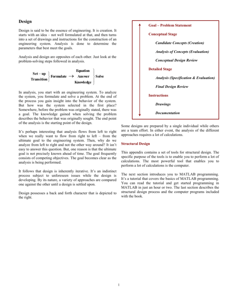
Design Goal – Problem Statement Design is said to be the essence of engineering. It is creation. It starts with an idea – not well formulated at that, and then turns into a set of drawings and instructions for the construction of an engineering system. Analysis is done to determine the parameters that best meet the goals. Conceptual Stage Candidate Concepts (Creation) Analysis of Concepts (Evaluation) Analysis and design are opposites of each other. Just look at the problem-solving steps followed in analysis. Set up Formulate Transition Equation Answer Knowledge Conceptual Design Review Detailed Stage Solve Analysis (Specification & Evaluation) Final Design Review In analysis, you start with an engineering system. To analyze the system, you formulate and solve a problem. At the end of the process you gain insight into the behavior of the system. But how was the system selected in the first place? Somewhere, before the problem was originally stated, there was a goal. The knowledge gained when solving the problem describes the behavior that was originally sought. The end point of the analysis is the starting point of the design. Instructions Drawings Documentation Some designs are prepared by a single individual while others are a team effort. In either event, the analysis of the different approaches requires a lot of calculations. It’s perhaps interesting that analysis flows from left to right when we really want to flow from right to left – from the ultimate goal to the engineering system. Then, why do we analyze from left to right and not the other way around? It isn’t easy to answer this question. But, one reason is that the ultimate goal is not precisely known ahead of time. The goal frequently consists of competing objectives. The goal becomes clear as the analysis is being performed. Structural Design This appendix contains a set of tools for structural design. The specific purpose of the tools is to enable you to perform a lot of calculations. The most powerful tool that enables you to perform a lot of calculations is the computer. It follows that design is inherently iterative. It’s an indistinct process subject to unforeseen issues while the design is developing. By its nature, a variety of approaches are compared one against the other until a design is settled upon. The next section introduces you to MATLAB programming. It’s a tutorial that covers the basics of MATLAB programming. You can read the tutorial and get started programming in MATLAB in just an hour or two. The last section describes the structural design process and the computer programs included with the book. Design possesses a back and forth character that is depicted to the right. 1 Computer Programs for Structural Analysis and Design truss2 Finds the forces and displacements in a planar truss The three major functions of a structure are strength, stiffness, and action. They serve as the structural designer’s primary goals. When developing designs that achieve these functions, the designer is faced with a set of secondary goals. They arise from practical limitations of cost and time and they’re a result of the physical limitations of materials. The secondary goals can lead to a desire to minimize the structure’s complexity, for example, the desire to use readily available materials and components and the goal to minimize the number of different types of structural elements and connections. truss3 Finds the forces and displacements in a space truss frame2 Finds the forces and displacements in a planar frame frame3 Finds the forces and displacements in a space frame Structural Design Process Section 5.5 shows how to uses these programs. To get a complete list of the input parameters and the output parameters in these programs, type help and program name. The following outlines a typical structural design process that would be followed by one or a team of engineers. The outline doubles as a Table of Contents for a structural design report. 1. 2. 3. 4. 5. 6. Section integrals are needed in stress analyses and mass integrals are needed in dynamic analyses. The computer programs listed below are used to calculate section integrals and inertia integrals of composite bodies. Goal – Problem Statement The original goal is stated along with how the goal evolved throughout the design process. Concepts Considered The different concepts are described. Concept Evaluation An analysis is performed of each concept. The performance of each concept is evaluated in a way that the degree to which the concept meets or does not meet the goal can be understood. Conclusions and Concept Selection The constraints in the problem are described. A winning concept is selected that best satisfies the goal and overcomes the constraints. Unresolved issues are identified. Detailed Analysis A detailed analysis is performed to overcome unresolved issues identified in the previous step and in order to complete the engineering specifications needed later for construction. Engineering Instructions A set of instructions, drawings and tables specify the engineering system so it can be constructed. The tables can include vendor information, parts lists, and a budget. Composite2 Calculates the section integrals of a composite body composite3 Calculates the inertia integrals of a composite body These two programs are described in Section 6.5. They assemble the composite body from the simple bodies cataloged in Table 1 in the back of the book. Type help and program name to get a complete list of the program’s input parameters and output parameters. Program List The two major types of structures are a truss and a frame. The computer programs listed to the right can be used to analyze them. 2
