Solutions
advertisement
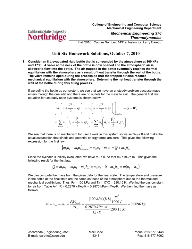
College of Engineering and Computer Science Mechanical Engineering Department Mechanical Engineering 370 Thermodynamics Fall 2010 Course Number: 14319 Instructor: Larry Caretto Unit Six Homework Solutions, October 7, 2010 1 Consider an 8 L evacuated rigid bottle that is surrounded by the atmosphere at 100 kPa and 17oC. A valve at the neck of the bottle is now opened and the atmospheric air is allowed to flow into the bottle. The air trapped in the bottle eventually reaches thermal equilibrium with the atmosphere as a result of heat transfer through the wall of the bottle. The valve remains open during the process so that the trapped air also reaches mechanical equilibrium with the atmosphere. Determine the net heat transfer through the wall of the bottle during this filling process. If we define the bottle as our system, we see that we have an unsteady problem because mass enters through the one inlet and there are no outlets for the mass to exit. The general first law equation for unsteady open systems is shown below. V2 V2 gz m1 u gz Q Wu m2 u 2 2 2 1 system Vi 2 Vi 2 mi hi gzi mi hi gzi 2 2 outlet inlet We see that there is no mechanism for useful work in this system so we set W u = 0 and make the usual assumption that kinetic and potential energy terms are zero. This gives the following expression for the first law. m2u2 m1u1 system m2u2 m1u1 Q minhin Since the cylinder is initially evacuated, we have m 1 = 0, so that m2 = min = m. This gives the following result for the first law. Q m2 u2 m1u1 min hin m2 u2 0 min hin mu2 hin We can compute the mass from the given data for the final state. The temperature and pressure in the bottle at the final state are the same as those of the atmosphere due to the thermal and mechanical equilibrium. Thus, P2 = 100 kPa and T2 = 17oC = 290.15 K. We find the gas constant for air from Table A-1: R = 0.2870 kJ/kg∙K = 0.2870 kPa∙m3/kg∙K. We then find the mass as follows: (100 kPa)(8 L) m min m2 m3 1000 L P2Vbottle 0.0096 kg 0.2870 kPa m 3 RT2 (290.15 K ) kg K Jacaranda (Engineering) 3519 E-mail: lcaretto@csun.edu Mail Code 8348 Phone: 818.677.6448 Fax: 818.677.7062 Unit six homework solutions ME 370, L. S. Caretto, Fall 2010 Page 2 We can use the ideal gas properties for air in Table A-17. For a temperature of 290.15, which is both the temperature of the inlet air and the final temperature in the cylinder, we find u2 = 206.91 kJ/kg and hin = 290.16 kJ/kg. We use these values and the mass to find the heat transfer. Q mu2 hin (0.0096 kg) 206.91 kJ 290.16 kJ = –0.8 kJ kg kg The minus sign shows that heat is transferred out of the bottle. 2 An insulated rigid tank is initially evacuated. A valve is opened and atmospheric air at 95 kPa and 17oC enters the tank until the pressure in the tank reaches 95 kPa, at which point the valve is closed. Determine the final temperature of the air in the tank. Assume constant specific heats. If we define the tank as our system, we see that we have an unsteady problem because mass enters through the one inlet and there are no outlets for the mass to exit. The general first law equation for unsteady open systems is shown below. 2 2 V V m2 u gz m1 u gz Q Wu 2 2 2 1 system 2 2 V V mo ho o gz o mi hi i gz i 2 2 outlet inlet We see that there is no mechanism for useful work in this system so we set W u = 0 and make the usual assumption that kinetic and potential energy terms are zero. This gives the following expression for the first law. m2u2 m1u1 system m2u2 m1u1 Q minhin Since the cylinder is initially evacuated, we have m 1 = 0, so that m2 = min = m. This gives the following result for the first law. Q m2 u2 m1u1 min hin m2 u2 0 min hin mu2 hin If we further assume that the “insulated” tank is so well insulated that the heat transfer is zero, the first law reduced to the following final form. Q mu2 hin 0 u2 hin We are told to use constant heat capacities; this allows us to compute changes in u or h from changes in temperature. But, here we have a difference between an internal energy and an enthalpy. We can use the relationship that the enthalpy definition, h = u + Pv, becomes h = u + RT for an ideal gas. Thus, we can rewrite the u2 = hin equation as follows. u2 hin uin RTin u2 uin RTin We can use the result that u = cvT for an ideal gas with constant heat capacity to obtain an equation to solve for the final temperature. Unit six homework solutions u2 uin cv T2 Tin RTin ME 370, L. S. Caretto, Fall 2010 T2 Tin Page 3 cp c R R Tin v Tin Tin kTin cv cv cv Here, we have used the definition of k as the ratio of heat capacities, k = c p/cv. From Table A-2(a) we find the value of k for air at 300 K is 1.4, so T2 = kTin = 1.4(290.15 K) = 406 K = 133oC. We see that the average temperature is (290 K+ 406 K)/2 = 348 K, We can check the value of k as a function of temperature from Table A2(b) and we see that it is still essentially 1.4 at this average temperature. 3 A 0.2 m3 rigid tank initially Inflow Pin = 1 MPa contains refrigerant-134a at oC T = 100 in 8oC. At this state 70% of the mass is in the vapor phase and the rest is in the liquid Q phase. The tank is connected by a valve to a Tank supply line the refrigerant at V = 0.2 m3 1 MPa and 100oC flows T1= 8oC steadily. Now the valve is x1 = 0.7 opened slightly and the refrigerant is allowed to enter the tank. When the pressure in the tank reaches 800 Pa, the entire refrigerant in the tank exists as a saturated vapor. At this point the valve is closed. Determine (a) the final temperature in the tank, (b) the mass of refrigerant that has entered the tank and (c) the heat transfer between the system and the surroundings. Since the final state is a saturated vapor, we know that the temperature must be the saturation temperature at the final pressure of 800 kPa. Thus, T2 = Tsat(P2 = 800 kPa) = 31.31oC , from Table A-12, page 928. If we define the tank as our system, we see that we have an unsteady problem because mass enters through the one inlet and there are no outlets for the mass to exit. The general first law equation for unsteady open systems is shown below. 2 2 V V m2 u gz m1 u gz Q Wu 2 2 2 1 system 2 2 V V o mo ho gz o mi hi i gz i 2 2 outlet inlet We see that there is no mechanism for useful work in this system so we set W u = 0 and make the usual assumption that kinetic and potential energy terms are zero. This gives the following expression for the first law. m2u2 m1u1 system m2u2 m1u1 Q minhin To find the mass added we simplify the general the mass balance equation for this problem where there is only one inlet. This gives the following result. Unit six homework solutions ME 370, L. S. Caretto, Fall 2010 m2 m1 system mi mo inlet Page 4 m2 m1 min outlet The initial mass, m1, is found from knowing the initial specific volume, v1, which is found from the initial temperature and quality as follows v1 v f (T1 8 o C ) x1 v g (v f (T1 8 o C ) v f (T1 8 o C ) 0.0007887 m 3 kg 3 3 0.037170 m 3 (0.7) 0.052762 m 0.0007887 m kg kg kg With this initial specific volume, we find the initial mass as follows. m1 0.2 m 3 V v1 0.037170 m 3 5.3807 kg kg At the final state, the specific volume is that of the saturated vapor; i.e., v2 = vg(P2 = 800 kPa) = 0.025621 m3/kg. We can use this specific volume to find the final mass in the tank. m2 0.2 m 3 V v 2 0.025621 m 3 7.8061 kg kg We can now find the added mass from our mass balance equation. min m2 m1 7.8061 kg 5.38068 kg = 2.43 kg . In order to compute the heat transfer we have to find the values of the energy properties. These are all found from the tables for R-134a. u1 u f (T1 8 o C ) x1u fg (T1 8 o C ) 62.39 kJ u2 = ug(P2 = 800 kPa) = 246.79 kJ/kg kg (0.7)172.19 kJ 182.92 kJ kg kg hin = h(1 MPa, 100oC) = 335.06 kJ/kg Substituting these property values and the values for the initial, final and added masses into the first law gives the heat transfer. Q m2 u 2 m1u1 system min hint (7.8061 kg) 246.79 kJ kg (5.38068 kg)182.92 kJ (2.4254 kg) 335.06 kJ kg kg Q = 130 kJ The positive sign for Q indicates that heat is added to the system. Unit six homework solutions 4 ME 370, L. S. Caretto, Fall 2010 Page 5 An insulated 60 ft3 rigid tank contains air at 75 psia and 120oF. A valve connected to the tank is now opened and air is allowed to escape until the pressure inside drops to 30 psia. The air temperature during this process is maintained constant by an electrical resistance heater placed in the tank. Determine the electrical work done during this process. If we define the tank as our system, we see that we have an unsteady problem because mass leaves through the one outlet and there are no inlets for the mass to enter. The general first law equation for unsteady open systems is shown below. 2 2 V V m2 u gz m1 u gz Q Wu 2 2 2 1 system 2 2 V V o mo ho gz o mi hi i gz i 2 2 outlet inlet We see that there is an electrical work input for the resistance “heater”. We will assume that the heat transfer is negligible for this insulated tank. We also make the usual assumption that kinetic and potential energy terms are zero. This gives the following expression for the first law. m2u2 m1u1 system m2u2 m1u1 Wu mouthout Our sign convention for work always assumes that W u is a work output. For this problem we expect W u to be negative since the problem statement that there is an input of electric power. In the general mass balance equation, shown below, we see that the left hand side is simply -mout, because there are no inlets and only one outlet. m2 m1 system mi mi mout inlet mout m1 m2 outlet We can find the initial and final mass in the tank from the ideal gas law. Table A-1E gives the gas constant for air as R = 0.3704 psia∙ft3/lbm∙R. m1 m2 P1Vtan k (75 psia )( 60 ft 3 ) 20.95 lbm 0.3704 psia ft 3 RT1 (579.67 R) lbm R P2Vtan k (30 psia )( 60 ft 3 ) 8.38 lbm 0.3704 psia ft 3 RT2 (579.67 R) lbm R The mass that left the tank is simply the difference between the initial and final mass: m out = m1 – m2 = 20.95 lbm – 8.38 lbm = 12.57 lbm. We can use the ideal gas properties for air from Table A17E. Since T1 = T2 = Tout= 120oF = 579.69 R, we have u1 = u2 =98.90 Btu/lbm and hout = 138.66 Btu/lbm. Plugging these properties and the masses found above into our first law equation gives the work. Unit six homework solutions ME 370, L. S. Caretto, Fall 2010 Wu m1u1 m2 u2 mout hout ( 20.95 lbm ) 98.90 Btu lbm (12.57 lb )138.66 Btu (8.38 lbm ) 98.90 Btu m lb lb m m Wu = –500 Btu As expected, the work is negative indicating that there is a work input of 500 Btu from the resistance heater. Page 6

