Frequency Modulated Vibrato
advertisement
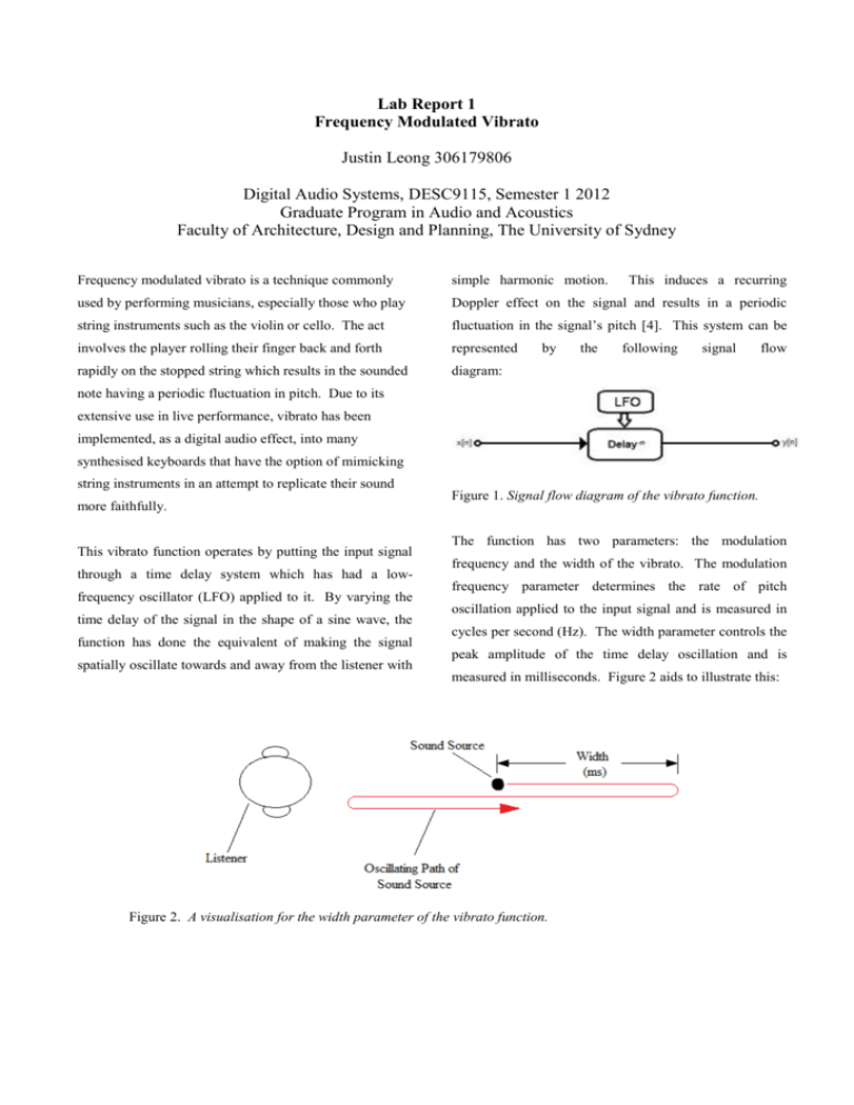
Lab Report 1 Frequency Modulated Vibrato Justin Leong 306179806 Digital Audio Systems, DESC9115, Semester 1 2012 Graduate Program in Audio and Acoustics Faculty of Architecture, Design and Planning, The University of Sydney Frequency modulated vibrato is a technique commonly simple harmonic motion. used by performing musicians, especially those who play Doppler effect on the signal and results in a periodic string instruments such as the violin or cello. The act fluctuation in the signal’s pitch [4]. This system can be involves the player rolling their finger back and forth represented rapidly on the stopped string which results in the sounded diagram: by the This induces a recurring following signal flow note having a periodic fluctuation in pitch. Due to its extensive use in live performance, vibrato has been implemented, as a digital audio effect, into many synthesised keyboards that have the option of mimicking string instruments in an attempt to replicate their sound more faithfully. This vibrato function operates by putting the input signal through a time delay system which has had a lowfrequency oscillator (LFO) applied to it. By varying the time delay of the signal in the shape of a sine wave, the function has done the equivalent of making the signal spatially oscillate towards and away from the listener with Figure 1. Signal flow diagram of the vibrato function. The function has two parameters: the modulation frequency and the width of the vibrato. The modulation frequency parameter determines the rate of pitch oscillation applied to the input signal and is measured in cycles per second (Hz). The width parameter controls the peak amplitude of the time delay oscillation and is measured in milliseconds. Figure 2 aids to illustrate this: Figure 2. A visualisation for the width parameter of the vibrato function. Increasing the width parameter will increase the apparent domain, this proves to be problematic because these distance through which the input signal oscillates and this, fractionally delayed samples have no output data in turn, will result in a greater variation in the pitch of the available to be assigned to them. To overcome this output signal. With this understanding of the parameters, problem, the function performs a linear interpolation the time delay function can basically be viewed as operation. This involves determining the distance that the follows: delayed sample lies between the two integer samples through the use of the floor function. i = floor(ZEIGER); frac = ZEIGER - i; Figure 3. It then constructs an imaginary straight line between the The modulation frequency is divided by a factor of the sampling frequency so that the modulation frequency parameter is measured in Hertz regardless of the input signal’s sampling rate. The “for loop” section of the Matlab code takes each individual sample of the input signal and alters the delay time of each in accordance with the sine wave function in neighbouring integer samples and uses this line to calculate an appropriate output value for the given fractionally delayed sample [3]. This takes place in the following line of code: y(n,1) = Delayline(i+1).*frac+Delayline(i).*(1frac); figure 3. In doing this, however, the function generates delay lengths that are not integer multiples of the sampling period (line 19 where the ZEIGER variable is calculated). Due to the discrete nature of the digital Figure 4 serves to aid in visualising the linear interpolation process: Figure 4. Shows how output signal values are calculated for fractionally delayed samples. It is clear that a faster sampling rate will increase the accuracy of this interpolation process. After each input sample has been operated on, the resulting output signal is normalised to produce the finished result. Appropriate values for the modulation frequency parameter are between 3 Hz – 8 Hz. Any values higher than 8 Hz start to produce unusual effects in the frequency content of the output signal. Suitable values for the width parameter are dependant on both the frequency content of the input signal and the value used for the modulation frequency parameter. For input signals with low frequency content, such as that of a double bass, a larger width value of 0.6-0.7 ms is required due to our logarithmic perception of pitch. For higher pitched instruments, such as the violin, a smaller width value of 0.3-0.4 ms will usually suffice. Also, as the modulation frequency of the vibrato is increased, the width parameter has to decrease slightly in order to preserve the natural timbre of the input signal. The input sound file included with this report is the file entitled ‘violin_openD.wav’ and the output sound file is entitled ‘violin_openD.vibrato.wav’. References [1] J. Dattorno, “Effect Design, Part 2: Delay-Line Modulation and Chorus,” J. Audio Eng. Soc., vol. 45, no. 10, pp. 764-769, Oct. 1997. [2] D. Marshall, “Tutorial 6: MATLAB Digital Audio Effects”, Cardiff University, Cardiff, Wales, http://www.cs.cf.ac.uk/Dave/Multimedia/PDF/06_CM0 340Tut_MATLAB_DAFX.pdf . [3] G. P. Scavone, “Delay Lines”, McGill University, Quebec, Canada, http://www.music.mcgill.ca/~gary/618/week1/delayline .html . [4] U. Zölzer, DAFX – Digital Audio Effects, John Wiley & Sons, West Sussex, England, 2002. MATLAB code sourced from: U. Zölzer, DAFX – Digital Audio Effects, John Wiley & Sons, West Sussex, England, 2002.


