Refraction
advertisement
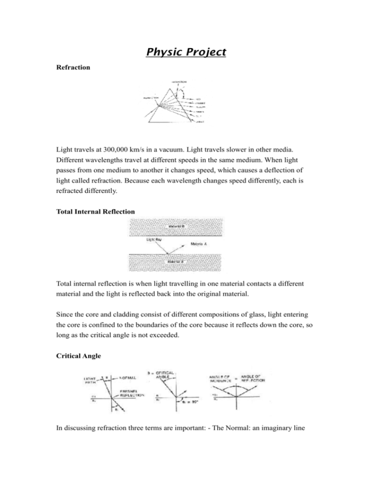
Physic Project Refraction Light travels at 300,000 km/s in a vacuum. Light travels slower in other media. Different wavelengths travel at different speeds in the same medium. When light passes from one medium to another it changes speed, which causes a deflection of light called refraction. Because each wavelength changes speed differently, each is refracted differently. Total Internal Reflection Total internal reflection is when light travelling in one material contacts a different material and the light is reflected back into the original material. Since the core and cladding consist of different compositions of glass, light entering the core is confined to the boundaries of the core because it reflects down the core, so long as the critical angle is not exceeded. Critical Angle In discussing refraction three terms are important: - The Normal: an imaginary line perpendicular to the interface of the two materials. - The Angle of Incidence: the angle between the incident ray and the normal.- The Angle of Reflection: the angle between the normal and the refracted ray. When light passes from one medium to another that has a higher refractive index, the light is refracted toward the normal. When the index of the first material is higher than that of the second, the light is refracted away from the normal (a small portion of the light is reflected back into the first material by Fresnel reflection). As the angle of incidence increases the angle of refraction approaches 90° with the normal. The angle which yields a 90° angle of refraction is called the critical angle. If the angle of incidence is increased past the critical angle the light is totally reflected back into the first material. The angle of reflection is equal to the angle of incidence. Numerical Aperture (NA) Numerical aperture (NA) is the light gathering capability of a fibre. The calculated material NA is related to the refractive indices of the core and cladding. A fibre with a high NA gathers more light than a fibre with a low NA because the critical angle is greater, and the fibre accepts light injected from larger angles. Acceptance Cone Since fibre is circular, a cone - the acceptance cone - defines the angles of incident light that are totally internally reflected by the core. A large acceptance cone, although allowing a fibre to accept and propagate light from a larger field, coincides with greater dispersion. Conversely, a narrow acceptance cone accompanies low dispersion but requires a narrow, more precise source of light Dispersion Dispersion relates to the spreading of the light pulse as it travels along the fibre. A pulse seen at the output is wider than the input pulse. Dispersion limits a fibres bandwidth. Pulse rates must be slow enough that dispersion does not cause adjacent pulses to overlap, the detector must be able to distinguish between each pulse Fibre Types Multimode Step Index, the simplest type has a core diameter in the 50um to more than 1000um range. The large core allows many modes of light propagation, some rays taking longer paths than others. The lowest order mode, the axial ray travelling down the centre of the fibre arrives at the end of the fibre before the higher order modes, spreading a narrow pulse of light as it travels through the fibre. This is called modal dispersion. Single Mode Step Index limits this dispersion by having a core small enough to allow only one mode of light to travel through the fibre. A single mode fibre with a core of Sum to 10um is very efficient for high speed, long distance applications. Multimode Graded Index fibre also limits dispersion. Its core is a series of concentric rings, each with a lower refractive index. Since light travels faster in a lower index medium, light farther away from the fibre axis travels faster. Rays of light are not reflected sharply by the core to cladding interface but are refracted successively by the differing layers of the core. Since the high order modes have a faster average velocity than the low order modes they arrive at any given point at nearly the same time. The path of travel appears almost sinusoidal. Intrinsic Attenuation Absorption Absorption is caused by impurities in the glass. Although glass fibres are ultrapure and have a purity exceeding that of semiconductors, some impurities remain as residue after purification. Absorption is caused by transition-metal ions of copper, iron, cobalt, and chromium and also by hydroxyl (OH-) ions associated with water molecules in the glass. The amount of absorption by these impurities depends on their concentration and the light wavelength. Intrinsic Attenuation Scattering Scattering results from imperfections in fibres and the basic structure of the fibre. Rayleigh scattering comes from the atomic and molecular structure of the glass and from density and composition variations that are natural by-products of manufacturing. Unintentional variations in density and fibre geometry occur during fibre manufacture and cabling. Small variations in the core diameter, microbends and small incongruities in the core diameter, microbends, and small incongruities in the core to cladding interface cause loss. The angle of incidence of rays striking such variations at the core to cladding interface change sufficiently that some rays are refracted onto new paths not subject to total internal reflection. Extrinsic Attenuation Macrobending Macrobending is loss due to large scale bending. Macrobending losses are reversible once bends are straightened. Installers can minimise the effect during installation and testing by not exceeding the installation and long term bend radii. Extrinsic Attenuation Macrobending Microbending is loss due to small scale bending or distortions. Microbending may not be visibly apparent. Microbending losses are reversible once cause is removed. Microbending may be: - temperature related. - tensile related. crush related. Installers can minimise this effect during installation and testing. Name : Au Ka Yiu Class number : F.3C 01


