Supplementary
advertisement
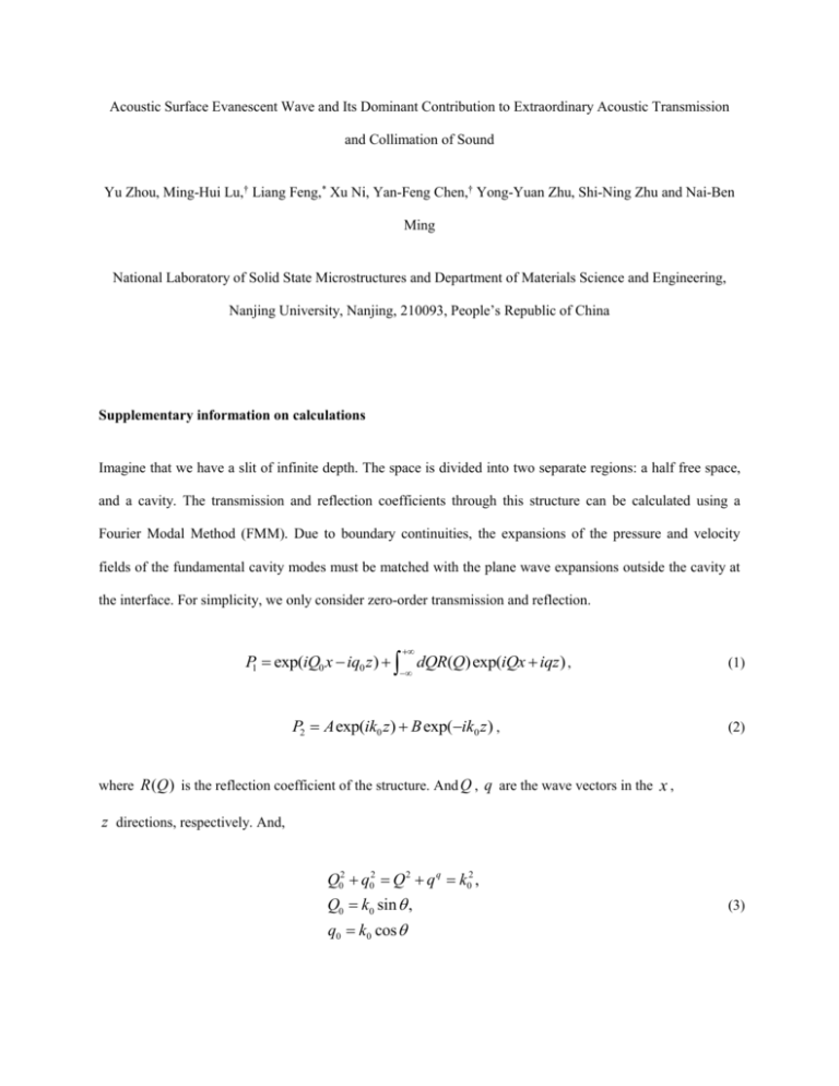
Acoustic Surface Evanescent Wave and Its Dominant Contribution to Extraordinary Acoustic Transmission and Collimation of Sound Yu Zhou, Ming-Hui Lu,† Liang Feng,* Xu Ni, Yan-Feng Chen,† Yong-Yuan Zhu, Shi-Ning Zhu and Nai-Ben Ming National Laboratory of Solid State Microstructures and Department of Materials Science and Engineering, Nanjing University, Nanjing, 210093, People’s Republic of China Supplementary information on calculations Imagine that we have a slit of infinite depth. The space is divided into two separate regions: a half free space, and a cavity. The transmission and reflection coefficients through this structure can be calculated using a Fourier Modal Method (FMM). Due to boundary continuities, the expansions of the pressure and velocity fields of the fundamental cavity modes must be matched with the plane wave expansions outside the cavity at the interface. For simplicity, we only consider zero-order transmission and reflection. P1 exp(iQ0 x iq0 z ) dQR(Q) exp(iQx iqz ) , P2 A exp(ik0 z ) B exp(ik0 z ) , (1) (2) where R (Q ) is the reflection coefficient of the structure. And Q , q are the wave vectors in the x , z directions, respectively. And, Q02 q02 Q 2 q q k02 , Q0 k0 sin , q0 k0 cos (3) From v P dt , we know that 0 v1 1 iq0 exp(iQ0 x iq0 z ) i q dQR(Q) exp(iQx iqz ) , v2 1 ik0 A exp(ik0 z ) ik0 B exp(ik0 z ) . (4) (5) First we are going to calculate the transmission coefficient of a normal incident plane wave. Because the cavity is of infinite depth, there's no reflection inside the cavity, so A 0 . And for normal incidence, we have Q0 0 , q0 k0 . According to the boundary conditions at z 0 , we have 1 dQR(Q) exp(iQx) B , (6) ik0 i q dQR(Q) exp(iQx) ik0 B . (7) In order to solve the coefficients, we can re-write R (Q ) in a zero-order form. R(Q) (Q Q0 ) R0W0 q , (8) where w W0 (Q) w 2 dx exp(iQx) . Combine these results, we get 2 (9) dQ R0W0 (Q) q exp(iQx) B 2 , (10) dQR0W0 (Q) exp(iQx) k0 B . (11) Make a Fourier Transformation to the last equation here, R0W0 (Q) 1 2 w w 2 dx(k0 B) exp(iQx) . (12) 2 Substitute into the first equation, we finally get B 2 , 1 G (13) where G k0 1 cos( wQ) dQ . w Q 2 k0 Q 2 B is in fact the transmission coefficient. So as stated in the main article, tn (14) 2 , rn tn 1 . Herein, G is 1 G equivalent to the definition of Eq. 5 of this paper (Phys. Rev. Lett. 101, 014301 (2008)), which means the transmission of single slit is originated from the coupling between the eigenmode of the slit and all the diffractive waves. Very similar calculations can be implemented to the grazing incident and cavity incident cases. We just have to change the initial conditions. For example, in grazing incident case, Q0 k0 , q0 0 . So finally we get all 6 coefficients, tn where F sinc 2 F G 1 , rn tn 1 , t g , rg t g 1 , rc , tc rc 1 , 1 G 1 G G 1 k0 w . 2 As soon as we acquire these coefficients, we can calculate the transmission and reflection of any complex structures using the combination of these results. For instance, if we have a slit with thickness h and width w , then all we need to do is to consider 2 separated interfaces at z 0 and z h . Suppose the incident wave has a pressure amplitude 1 . We denote the wave going forward in the cavity as B , and backward as A . B Arc tn , (15) r rn Atc , (16) B exp 2 (ik0 h)rc A . (17) So we get the total reflection coefficient of this structure r rn tntc rc exp(2ik0 h) 1 exp(2ik0 h)rc2 . (18) Here, we define Gslit tc exp(2ik0 H ) / [1 exp(2ik0 H ) rc ] and Ggv tc exp(2ik0 h) / [1 exp(2ik0 h)rc ] . 2 So we have Pslit P0 (tn rcGslit rn ) and Pgv P0 (tn Ggv rn ) . (19) Next, we consider CWs and ASEWs in the way that’s described in the manuscript. m x exp(ik0 x) , (20) PASEW ( x) Ps AASEW ( x) Ps ASEW exp(ik ASEW x) , (21) PCW ( x) PS ACW ( x) PS CW where 2 k ASEW k0 w 1 tan(k0 h) . d (22) Considering the whole structure, we have to view every groove spot on the slit as an independent structure, which is capable of scattering an incident wave and generating CWs and ASEWs. Using the results above, we can get the pressure field of the acoustic wave inside the central slit, 9 Pf P0tn 2t g Pn Atot (nd ) Gslit exp(ik0 H ) , n 1 (23) where, 9 Pn P0 (tnGgv rn ) (t g Ggv rg ) P0 (tn rc Gslit rn ) Atot (nd ) P0 (tnGgv rn ) Atot ( m n ) , m 9 m 0, n (24) is the contribution from the nth groove on the input side. Similarly, the groove spots on the output side of the structure also provide the same scattering mechanism. We have 9 P( x, z ) Pf ACW x 2 z 2 Pn' ACW ( x nd ) 2 z 2 , (25) n 9 n0 where, Pn' Pf (tg Ggv rg )Atot (nd ) . Then, according the above equations, we can obtain the transmission spectra and the spatial distribution of pressure fields. (26) 1 r AB t Supplementary Figure S1: Schematic of our theory model. The pressure field of incident waves are normalized 1; A and B denote the pressure field of forward waves and backward waves respectively; t means transmissivity and r means the reflectivity. Supplementary Figure S2: Schematics of the experimental setup. The first experimental setup is used to measure the transmission spectra of ultrasonic waves through our sample. The second one is used to map the sound field behind the sample. It consists of two transducers, a function generator, and an oscilloscope for pulse measurement or a lock in amplifier for continuous wave measurement.

