File - Pragati fast updates
advertisement
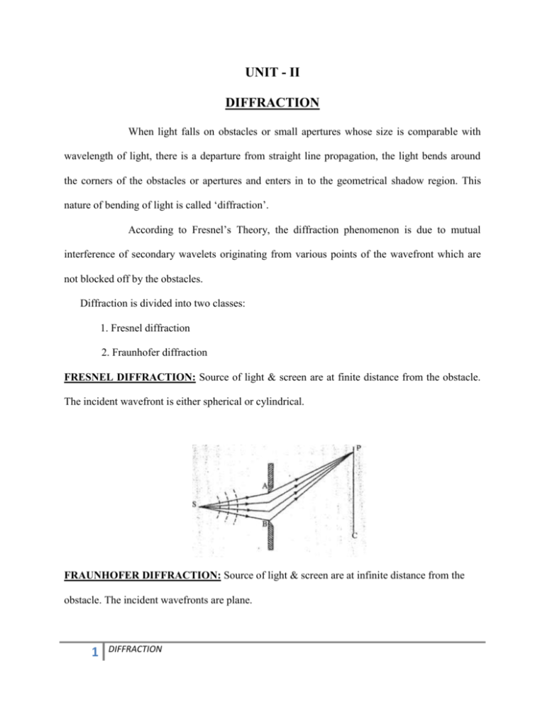
UNIT - II DIFFRACTION When light falls on obstacles or small apertures whose size is comparable with wavelength of light, there is a departure from straight line propagation, the light bends around the corners of the obstacles or apertures and enters in to the geometrical shadow region. This nature of bending of light is called ‘diffraction’. According to Fresnel’s Theory, the diffraction phenomenon is due to mutual interference of secondary wavelets originating from various points of the wavefront which are not blocked off by the obstacles. Diffraction is divided into two classes: 1. Fresnel diffraction 2. Fraunhofer diffraction FRESNEL DIFFRACTION: Source of light & screen are at finite distance from the obstacle. The incident wavefront is either spherical or cylindrical. FRAUNHOFER DIFFRACTION: Source of light & screen are at infinite distance from the obstacle. The incident wavefronts are plane. 1 DIFFRACTION Fresnel diffraction is a general case and involves oblique angles of incidence while Fraunhofer diffraction simplifies diffraction to normal incidence. By using bi-convex lenses, finite distances can be made infinite & hence in a Lab, one can achieve Fraunhofer condition from Fresnel conditions. Fraunhofer diffraction is a special case of Fresnel diffraction, DIFFERENCES BETWEEN INTERFERENCE AND DIFFRACTION: 1. In the interference, the interaction takes place between two separate wavefronts originating from the coherent sources. In the case of diffraction the interaction takes between the secondary wavelets originating from different points of the exposed parts of the same wave front. 2. The region of minimum intensity are usually almost perfect dark. The position of minimum intensity are not perfectly dark. 3. The width of the fringes may or may not be equal or unequal. The fringe width of various fringes is never equal. 4. In the interference pattern all the maxima are of the same intensity. In the diffraction pattern all the maxima are not of the same intensity. 2 DIFFRACTION FRAUNHOFER DIFFRACTION DUE TO TWO PARALLEL SLITS: Let AB and CD be two parallel slits of equal width a and separated by an opaque distance e. The distance between the corresponding middle points of the two slits is (a+e) as shown in the figure. Let a parallel beam of monochromatic light of wavelength λ be incident normally upon the two slits. The light diffracted from these slits is focused by a lens on the screen XY placed in the focal plane of lens. The diffraction at two slits is the combination of diffraction as well as interference. When a plane wave front of wavelength λ is incident normally on the slits, all points within the slits become the source of secondary wavelets which travels in all directions. The secondary wavelets travelling in the direction of incident light come to focus at Po, while the secondary wavelets travelling in a direction making an angle θ with the incident direction come to focus at P1. According to the theory of diffraction at a single slit, the resultant amplitude (R) due to all wavelets diffracting from each region of slit in a direction θ is given by 3 DIFFRACTION R= A0 , aSin Where A0=Aa and = The resultant amplitude at P1 will be result of interference between two waves of amplitude A0 and having phase difference ∆= 2 ( a e) Sin The resultant amplitude R1 is obtained with the help of the following diagram . R1 R 2 2 RR Cos R 2 2 4 R 2 Cos 2 I 4I 0 2 Sin 2 2 Cos 2 2 From the above equation the intensity in the resultant pattern depends upon the following two factors 1. I0 gives the intensity distribution in the diffraction due to individual slit. 2. Cos2 gives the interference pattern due to two parallel slits The diffraction term gives the central maximum in the direction θ=0, having alternate minima and secondary maxima of decreasing intensity on either sides as shown figure. The minimum occurs at asingθ=±mλ The positions of secondary maximum β=±1.43π, ±2.46π, ±3.47π………. The interference maxima occurs when Cos2 =1 4 DIFFRACTION Therefore, (a+e)sinθ=±nλ The interference minima are obtained when Cos2 =0 Therefore, (a+e)sinθ= ± (2n+1)λ/2 The resultant pattern is shown in the following graph. DIFFRACTION GRATING: An arrangement consists of large number of parallel slits of the same width and separated by equal opaque space is known as diffraction grating. The corresponding diffraction pattern is known as diffraction spectrum. According to the equation (a+e)sinθ=nλ, the exact position of the principal maxima in the diffraction pattern depend on the wavelength, the principal maxima corresponding to different spectral lines will correspond to different angles of diffraction. Thus the grating spectrum provides us with an easily obtainable experimental setup for the determination of the wavelength. 5 DIFFRACTION For sharp spectral lines a large vale of N is required. A good quality of grating therefore requires a large number of slits. This can be achieved by ruling grooves with a diamond point on an optically transparent with material. The grooves acts as opaque spaces, commercial gratings are produced by a solution of cellulose acetate of appropriate strength is poured on the related surface and allowed to dry to form a strong thin film, detachable from the parent grating. These impressions of a grating are preserved by mounting the film between to glass sheets. Now a days gratings have a much larger number of lines/cm GRATING SPECTRUM: The position of principal maxima of a grating is given by the equation. (a+e)sinθ=nλ This equation is also known as grating equation. This equation show s the dependence of diffraction angle θ on wavelength λ The zero order principal maximum occurs at θ=0, irrespective of wavelength. Thus if we send the white light, then central maximum will also white. For n is not equal to zero the angle of diffraction are different for different wavelength and hence various spectral components appear at different postions. Thus by measuring the angles of diffraction for various colours and knowing the values of n one can determine the wavelength values. The intensity is maximum for the zero order maximum and it falls off as the value of n increases. If we differentiate the above equation we get = From the above equation we can find the following coclutions. 6 DIFFRACTION 1. if θ is very small for a given values of ∆λ the angle ∆θ is directly proportional to order. For a given value of n, is constant. Such spectrum is known as normal spectrum. Difference in the angle for two spectral lines is directly proportional to difference in wavelength. 2. From the above equation ∆θ is inversely proportional to (a+e), the grating element. Smaller the grating element greater will be the angular dispersion. RAYLEIGH CRITERION FOR RESOLVING POER: According to Rayleigh criterion, two sources are resolvable by an optical instrument when the central maximum in the diffraction pattern of one falls over the first minimum in the diffraction pattern of the other vice-versa. Let us consider the resolving of two wavelengths λ1 and λ2 by grating. Figure 1. Shows the intensity pattern due to two wavelengths. The difference in wavelength is such that their principal maxima are separately visible. Hence two wavelengths are resolved. When the difference in wavelength is small and such that the central maximum of wavelengths coincides with the first minimum of the other shown in figure 2. The resultant intensity curve is shown by thick curve. The curve shows a distinct dip in the middle of two central maxima ie there is a noticeable decrease in intensity between the two central maxima indicating the presence of two different wavelengths. Thus the two wavelengths can be distinguished from one another and they are said to just resolved. 7 DIFFRACTION Fig1 Fig2 Fig3 When the difference in wavelength is so small, that the central maximum corresponding to two wavelengths come closer as shown in figure 3. The resultant intensity cureve giving the impression as if there is only one wavelength source. Hence two wavelengths are not resolved. The minimum angle of resolution provided by lens of diameter D at wavelength λ is min 1.22 D RESOLVING POWER OF A GRATING: The resolving power of a grating refers to the power of distinguishing two nearby spectral lines. This is defined by the following equation Resolving Power R = Where ∆λ is the difference in two wavelengths. From the above equation the smaller the vales of ∆λ , the larger the resolving power. Let a parallel beam of light of two wavelengths λ and λ+dλ be incident normally on the grating. If the n th principal maximum of λ is formed in the direction θn, we have (a+e)sin θn=nλ Where (a+e) is grating element The first minimum adjacent to the n th maximum is obtained in the direction (θn+dθ). The equation for that minimum is N(a+e)sin (θn+dθ) =(nN+1)λ -----------(1) Where N is the total number of lines on the grating 8 DIFFRACTION According to Rayleigh’s criterion, if the principal maximum corresponding to wavelength (λ+dλ) falls on the first minimum of wavelength λ then the wavelength are said to be resolved. nth maximum of λ+dλ in the direction of (θn+dθ) is (a+e)sin θn=n( λ+dλ) -------------(2) Multiplying the above equation with N N(a+e)sin θn=n( λ+dλ)N ------------(3) From the above equations (1) and (2) Resolving Power R = = Nn Thus the resolving power of the grating is equal to the product of the total number of lines N on the grating and the order of the spectrum. The resolving power for zero order is zero, because n=0 FRAUNHOFER DIFFRACTION DUE TO ‘N’ PARALLEL SLITS N number of equidistant and equally wide slits are represented in the below figure. The slit lengths are perpendicular to the paper. Widths are all equal to ‘a’ and the separation between the slits is equal to‘e’. This arrangement is illuminated by a monochromatic beam of light of wavelength λ falling normally from the left. Therefore, each of the slit sends secondary wavelets in all directions. The secondary wavelets traveling in the same direction of incident light will come to focus at point P0. The point P0 will be a central maximum. 9 DIFFRACTION Now consider the secondary wavelets traveling in direction inclined at an angle θ with the direction of the incident light. The waves reach point P 1 in different phase. As a result dark and bright bands on the both sides of the central maximum are obtained. There N slits, then we have N diffracted waves each of amplitude R Ao And having successive phase difference 2 sin (a e) sin The resultant disturbance ‘y’ due to N diffracted waves at P1 is given by y R cos t cos(t ) cos(t 2) ......N terms = Real part of Re it 1 e i e 2i .....N terms 1 e iN = Re iwt i 1 e To find the intensity, we multiply the amplitude with its complex conjugate; 10 DIFFRACTION (1 e iN )(1 e iN ) A2 I R 2 i i (1 e )(1 e ) 1 cos N 2 = R2 R 1 cos I Io sin 2 2 N 2 sin 2 2 sin 2 sin 2 N sin 2 where (a e) sin As can be seen the intensity distribution is a product of two terms. The first term represents diffraction produced by a single slit and the second term represents the interference produced by multiple slits These intensities would be maximum for Sinα=0 or α=kπ wherek=0,1,2,3….. The resultant intensity is I O sin 2 2 N 2 (Principal Maxima) The maxima are obtained for α=nπ (a+e)sinθ=nλ This equation is know as grating equation n=o corresponding to zero order maximum, for n=1,2,3,….. we obtain first order, second order, third order To find out secondary maxima position we differentiate the equation I with respect to α and equate to zero N Tanα=TanNα 11 DIFFRACTION The roots of this equation other than those for which α=nπ gives the position of secondary maxima. The pattern is shown in the following figure. 12 DIFFRACTION

