04.05.09 - University of Manchester
advertisement
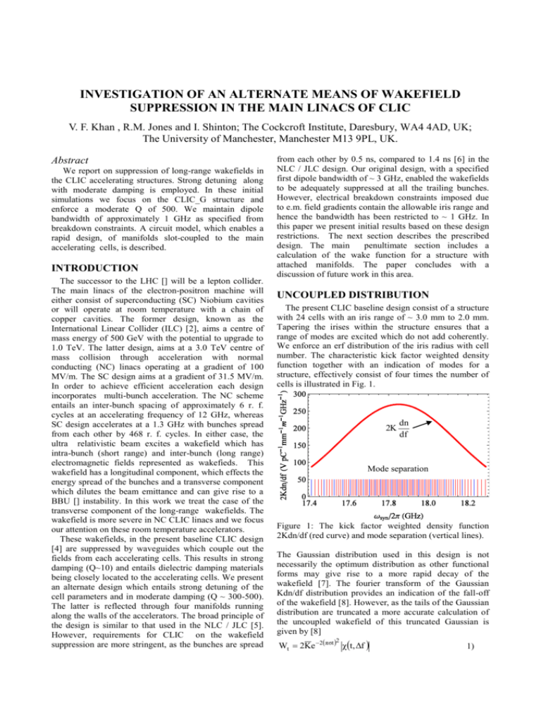
INVESTIGATION OF AN ALTERNATE MEANS OF WAKEFIELD SUPPRESSION IN THE MAIN LINACS OF CLIC V. F. Khan , R.M. Jones and I. Shinton; The Cockcroft Institute, Daresbury, WA4 4AD, UK; The University of Manchester, Manchester M13 9PL, UK. Abstract We report on suppression of long-range wakefields in the CLIC accelerating structures. Strong detuning along with moderate damping is employed. In these initial simulations we focus on the CLIC_G structure and enforce a moderate Q of 500. We maintain dipole bandwidth of approximately 1 GHz as specified from breakdown constraints. A circuit model, which enables a rapid design, of manifolds slot-coupled to the main accelerating cells, is described. INTRODUCTION The successor to the LHC [] will be a lepton collider. The main linacs of the electron-positron machine will either consist of superconducting (SC) Niobium cavities or will operate at room temperature with a chain of copper cavities. The former design, known as the International Linear Collider (ILC) [2], aims a centre of mass energy of 500 GeV with the potential to upgrade to 1.0 TeV. The latter design, aims at a 3.0 TeV centre of mass collision through acceleration with normal conducting (NC) linacs operating at a gradient of 100 MV/m. The SC design aims at a gradient of 31.5 MV/m. In order to achieve efficient acceleration each design incorporates multi-bunch acceleration. The NC scheme entails an inter-bunch spacing of approximately 6 r. f. cycles at an accelerating frequency of 12 GHz, whereas SC design accelerates at a 1.3 GHz with bunches spread from each other by 468 r. f. cycles. In either case, the ultra relativistic beam excites a wakefield which has intra-bunch (short range) and inter-bunch (long range) electromagnetic fields represented as wakefieds. This wakefield has a longitudinal component, which effects the energy spread of the bunches and a transverse component which dilutes the beam emittance and can give rise to a BBU [] instability. In this work we treat the case of the transverse component of the long-range wakefields. The wakefield is more severe in NC CLIC linacs and we focus our attention on these room temperature accelerators. These wakefields, in the present baseline CLIC design [4] are suppressed by waveguides which couple out the fields from each accelerating cells. This results in strong damping (Q~10) and entails dielectric damping materials being closely located to the accelerating cells. We present an alternate design which entails strong detuning of the cell parameters and in moderate damping (Q ~ 300-500). The latter is reflected through four manifolds running along the walls of the accelerators. The broad principle of the design is similar to that used in the NLC / JLC [5]. However, requirements for CLIC on the wakefield suppression are more stringent, as the bunches are spread from each other by 0.5 ns, compared to 1.4 ns [6] in the NLC / JLC design. Our original design, with a specified first dipole bandwidth of ~ 3 GHz, enabled the wakefields to be adequately suppressed at all the trailing bunches. However, electrical breakdown constraints imposed due to e.m. field gradients contain the allowable iris range and hence the bandwidth has been restricted to ~ 1 GHz. In this paper we present initial results based on these design restrictions. The next section describes the prescribed design. The main penultimate section includes a calculation of the wake function for a structure with attached manifolds. The paper concludes with a discussion of future work in this area. UNCOUPLED DISTRIBUTION The present CLIC baseline design consist of a structure with 24 cells with an iris range of ~ 3.0 mm to 2.0 mm. Tapering the irises within the structure ensures that a range of modes are excited which do not add coherently. We enforce an erf distribution of the iris radius with cell number. The characteristic kick factor weighted density function together with an indication of modes for a structure, effectively consist of four times the number of cells is illustrated in Fig. 1. 2K dn df Mode separation Figure 1: The kick factor weighted density function 2Kdn/df (red curve) and mode separation (vertical lines). The Gaussian distribution used in this design is not necessarily the optimum distribution as other functional forms may give rise to a more rapid decay of the wakefield [7]. The fourier transform of the Gaussian Kdn/df distribution provides an indication of the fall-off of the wakefield [8]. However, as the tails of the Gaussian distribution are truncated a more accurate calculation of the uncoupled wakefield of this truncated Gaussian is given by [8] Wt 2Ke 2πσt χ t, Δf 2 1) where K is the average kick factor and the χ factor is defined by: Re erf f i42 t / 2 2 t, f erf f / 2 2 2) Here, f represents to the bandwidth of the Kdn/df distribution. f f 2 c dn K 2 K N e 2 3) df 2 We chose a bandwidth of 3.0σ or ~5.0% of the central frequency. In order to calculate the long-range behaviour of the wake function wee utilise a circuit model which includes TE-TM dipole modes coupled via TE modes to a manifold through slot-cut in to each cell. This circuit model includes a double band chain of L-C circuit capacitively coupled to a transmission line [5]. The wakefield is calculated by α-spectral method which requires f parameters and the corresponding kick factors to be obtained for each cell of the accelerating structure. We parameterise the structure by choosing seven fiducial cells and all the parameters of the other cells are obtained by cubic spline interpolation. The procedure allows an efficient determination of the wakefield. The parameters are subsequently made functionally dependent on the synchronous frequencies of each cells and thus allows a rapid evaluation of the wakefield of new distributions. The parameters of each cell are obtained through solving eight coupled non-linear equations for each fiducial cell subjected to infinite periodic boundary conditions. The circuit equation describing a dipole mode of frequency f coupled to the manifold at a phase advance per cell of ψ is given by[5]: 1 η cos ψ/ f 1 η̂ cos ψ 2 0 / f̂ 02 cos ψ - cos φ / f f̂ sin ψ (dashed) curves represent the coupled (uncoupled) dipole modes. All the points have been obtained with HFSSv11 operated in to eigen mode module. The red points are used in solving the coupled non-linear equation and the curves are required to pass through these points. The additional (black) points provide an indication as to the quality of the fits and are not used in the parameter determination. The field distribution of the lower zero and the lower pi mode are illustrated in Fig. 3. Manifold Coupling slot a) b) Figure 3: Electric field in CLCI_DDS at zero phase advance (a) and pi phase advance (b), corresponding to ω/2π = 14.37 GHz and 17.41 GHz respectively. The dipole mode excited at the point where the light line intersects the modal curves and synchronous point. This is in the vicinity of a pi phase advance and the *** ** ** the expected field in this region. The modes subsequently travels down the accelerating structure and couples out to the manifold through slots downstream. This allows the coupled wakefield to be determined and this described in the next section 2 / α / F 2 f 2 f -2 f -2 η 2x DISCUSSION 2 0 0 4) 2 F 2 / F 2 f 2 πL/c 2 1 η̂ cos ψ f̂ 0-2 f̂ -2 sincφ where all parameters are described in [5]. The corresponding Brillouin diagram of the first cell of the CLIC_DDS design is illustrated in Fig. 2. Application of the spectral function method structures to be ***** designed which will suppress the wake function in the CLIC main linacs. The initial design presented here, is modified by a design to reduce the maximum pulse temperature rise on the wall of the cavity and to remotely located the HOM loads. Four-fold interleaving of the erf distribution of frequencies of successive structure is employed. This design can benefit from additional optimisation. Further designs are anticipated utilising different Kdn/df distribution and will benefit from slightly increased bandwidth which are under active consideration. Furthermore, we are now in a position to perform an optimisation of provided manifold to cell coupling and on means to further reduce the magnetic field in the vicinity of the coupling slots where it is maximum with respect to the whole structure. ACKNOWLEDGMENTS Figure 2: Brillouin diagram for the first cell of CLIC_DDS. The points represent simulation and solid Useful discussions have been conducted with W. Wuensch, A. Grudiev, J. Wang and T. Higo regarding the X-band structures. The research leading to these results has received funding from European commission under the FP7 research infrastructure grant agreement no. 227579. V. Khan is thankful to The Cockcroft Institute for supporting to pursue PhD in accelerator physics field. REFERENCES [1] http://www.linearcollider.org [2] [3] [4] H. Braun, et al, CLIC-Note 764, 2008 [5] R.M. Jones, et al, 2006, Phys. Rev. STAB, 9, 102001. [6] J.W. Wang and T. Higo, SLAC-PUB-10370, 2004 [7] R.M.Jones, et al, 2000, SLAC-PUB-8609, LINAC00 [8] V.F. Khan and R.M. Jones, 2008, WEPP089, EPAC08


