inverse scattering of buried inhomogeneous dielectric material
advertisement
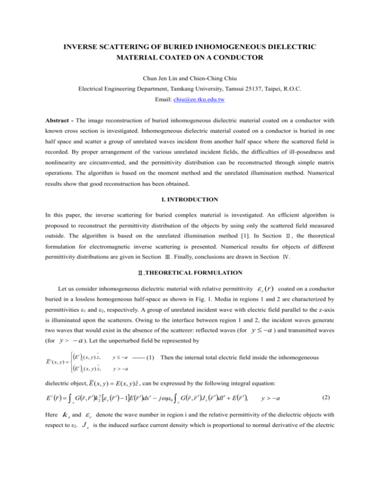
INVERSE SCATTERING OF BURIED INHOMOGENEOUS DIELECTRIC MATERIAL COATED ON A CONDUCTOR Chun Jen Lin and Chien-Ching Chiu Electrical Engineering Department, Tamkang University, Tamsui 25137, Taipei, R.O.C. Email: chiu@ee.tku.edu.tw Abstract - The image reconstruction of buried inhomogeneous dielectric material coated on a conductor with known cross section is investigated. Inhomogeneous dielectric material coated on a conductor is buried in one half space and scatter a group of unrelated waves incident from another half space where the scattered field is recorded. By proper arrangement of the various unrelated incident fields, the difficulties of ill-posedness and nonlinearity are circumvented, and the permittivity distribution can be reconstructed through simple matrix operations. The algorithm is based on the moment method and the unrelated illumination method. Numerical results show that good reconstruction has been obtained. I. INTRODUCTION In this paper, the inverse scattering for buried complex material is investigated. An efficient algorithm is proposed to reconstruct the permittivity distribution of the objects by using only the scattered field measured outside. The algorithm is based on the unrelated illumination method [1]. In Section Ⅱ, the theoretical formulation for electromagnetic inverse scattering is presented. Numerical results for objects of different permittivity distributions are given in Section Ⅲ. Finally, conclusions are drawn in Section Ⅳ. Ⅱ.THEORETICAL FORMULATION Let us consider inhomogeneous dielectric material with relative permittivity r (r ) coated on a conductor buried in a lossless homogeneous half-space as shown in Fig. 1. Media in regions 1 and 2 are characterized by permittivities ε1 and ε2, respectively. A group of unrelated incident wave with electric field parallel to the z-axis is illuminated upon the scatterers. Owing to the interface between region 1 and 2, the incident waves generate two waves that would exist in the absence of the scatterer: reflected waves (for (for y > y a ) and transmitted waves a ). Let the unperturbed field be represented by i E 1 ( x, y ) z, E ( x, y ) E i ( x, y ) z, 2 i y a ------ (1) Then the internal total electric field inside the inhomogeneous y a dielectric object, E ( x, y) E ( x, y) zˆ , can be expressed by the following integral equation: E i r Gr , r k 22 r r 1E r ds j 0 G r , r J s r dl E r , c s Here k i and respect to ε2. r y a (2) denote the wave number in region i and the relative permittivity of the dielectric objects with J s is the induced surface current density which is proportional to normal derivative of the electric field on the conductor surface. G ( x, y; x' , y ' ) is the Green’s function. The boundary condition states that the total tangential electric field must be zero on the surface of the perfectly conducting cylinder and this yields the following equation: E i r Gr , r k 22 r r 1E r ds j 0 G r , r J s r dl , y a c s (3) The scattered field can be expressed as E s r G r , r k 22 r r 1E r ds j 0 G r , r J s (r )dl s (4) c For the direct scattering problem, the scattered field is computed by giving the permittivity distribution of the buried inhomogeneous dielectric cylinders coated on a conductor objects. This can be achieved by using (2) and (3) to solve the total field inside the object E and calculating E s by (4). Thus the permittivity and the total field within each cell can be taken as constants. Then the moment method is used to solve (2), (3) and (4) with a pulse basis function for expansion and point matching for testing [2]. Thus the following matrix equations can be obtained: ( E i ) [G1 ][ ] [ I ]( E) [G2 ] ( J s ) ----------(5), ( Evi ) [G3 ][ ] ( E ) [G4 ] ( J s ) -----------(6) ( E s ) [G5 ][ ] ( E) [G6 ] ( J s ) ----------(7) We consider the following inverse problem: the permittivity distribution of the inhomogeneous dielectric material coated on a conductor objects is to be computed by the knowledge of the scattered field measured in region 1. Note that the only unknown permittivity is r (r ) . In the inversion procedure, we choose N1 different incident column vectors. Then (5)-(7) can be expressed as s [ E ip ] [G p1 ][ ] [ I ] [ E ] ---(8), [ E p ] [G p 2 ][ ][ E] ---(9) Region 1 ε1 where Y= - a Region 2 ε2 Dielectric Material [ E ip ] [ E i ] [G2 ][G4 ]1 [ Evi ] , [ E ps ] [ E s ] [G6 ][G4 ]1 [ Evi ] , 1 1 [G p1 ] [G1 ] [G2 ][G4 ] [G3 ] , [G p 2 ] [G6 ][G4 ] [G3 ] [G5 ] Co ndu cto r X Therefore, by first solving [E ] in (9) as well and substituting into (9). Then [τ] can be found by solving the following equations: [ ][ ] [] ------------ (10) where i 1 , p [] [ E ][ E ] s p Y i 1 p [] [ E ][ E ] [G p1 ] [G p 2 ] s p Fig. 1 Geometry of problem in the (x,y) plane From (10), all the diagonal elements in the matrix [τ] can be determined by comparing the element with the same subscripts, which may be any row of both [ ] and [ ] : nn mn mn ----------------(11) Note that there are a total of M possible values for each element of τ. Therefore, the average value of these M data is computed and chosen as final reconstruction result in the simulation. Ⅲ. NUMERICAL RESULTS In this section, we report some numerical results obtained by computer simulations using the method described in the Section Ⅱ. Let us consider an inhomogeneous dielectric cylinders coated on a conductor buried at a depth of a = 0.1m in a lossless half space, as shown in Fig. 1. The permittivities in region 1 and 2 are characterized by ε1= ε0 and ε2= 2.25ε0. The frequency of the incident waves is chosen to be 3GHz and the number of illuminations is the same as that of cells. The incident waves are generated by numerous groups of radiators operated simultaneously. The measurement is taken on a half circle of radius 3m about (0, a ) at equal spacing. The number of measurement point is set to be 8 for each illumination. In the example, the buried cylinder with a 2.4 × 4.8 cm rectangular cross section is discretized into 8 × 16 cells, and the corresponding dielectric permittivities are plotted in Fig. 2. The model is characterized by simple step distribution of permittivity. Each cell has 0.3 × 0.3 cm cross-sections. The reconstructed permittivity distributions of the object are plotted in Fig. 3. The root-mean-square (RMS) error is about 1.1%. It is clear that the reconstruction is good. Fig. 2 Original relative permittivity distribution Fig. 3 Reconstructed relative permittivity distribution Ⅳ. CONCLUSIONS An efficient algorithm for reconstructing the permittivity distribution of buried inhomogeneous dielectric cylinders coated on a conductor has been proposed. The moment method has been used to transform a set of integral equations into matrix form. Then these matrix equations are solved by the unrelated illumination method. Numerical simulation for imaging the permittivity distribution of a buried inhomogeneous dielectric cylinders coated on a conductor has been carried out and good reconstruction has been obtained even in the presence of Gaussian noise in measured data. This algorithm is very effective and efficient, since no iteration is required. REFERENCES 1. W. Wang and S. Zhang, “Unrelated illumination method for electromagnetic inverse scattering of inhomogeneous lossy dielectric bodies,” IEEE Trans. Antennas and Propagation, Vol. AP-40, pp. 1292-1296, Nov. 1992. 2. R. F. Harrington, “Field Computation by Moment Methods,” New York: Macmillan, 1968.
