Schedule
advertisement
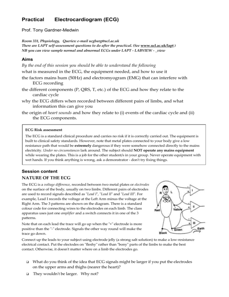
Practical Electrocardiogram (ECG) Prof. Tony Gardner-Medwin Room 331, Physiology, Queries: e-mail ucgbarg@ucl.ac.uk There are LAPT self-assessment questions to do after the practical. (See www.ucl.ac.uk/lapt ) NB you can view sample normal and abnormal ECGs under LAPT - LABVIEW - _view Aims By the end of this session you should be able to understand the following what is measured in the ECG, the equipment needed, and how to use it the factors mains hum (50Hz) and electromyogram (EMG) that can interfere with ECG recording the different components (P, QRS, T, etc.) of the ECG and how they relate to the cardiac cycle why the ECG differs when recorded between different pairs of limbs, and what information this can give you the origin of heart sounds and how they relate to (i) events of the cardiac cycle and (ii) the ECG components. ECG Risk assessment The ECG is a standard clinical procedure and carries no risk if it is correctly carried out. The equipment is built to clinical safety standards. However, note that metal plates connected to your body give a low resistance path that would be extremely dangerous if they were somehow connected directly to the mains electricity. Under no circumstances lark around. The subject should NOT operate any mains equipment while wearing the plates. This is a job for the other student/s in your group. Never operate equipment with wet hands. If you think anything is wrong, ask a demonstrator - don't try fixing things. Session content NATURE OF THE ECG The ECG is a voltage difference, recorded between two metal plates or electrodes on the surface of the body, usually on two limbs. Different pairs of electrodes are used to record signals described as "Lead I", "Lead II" and "Lead III". For example, Lead I records the voltage at the Left Arm minus the voltage at the Right Arm. The 3 patterns are shown on the diagram. There is a standard colour code for connecting wires to the electrodes on each limb. The class apparatus uses just one amplifier and a switch connects it in one of the 3 patterns. Note that on each lead the trace will go up when the "+" electrode is more positive than the "-" electrode. Signals the other way round will make the trace go down. Connect up the leads to your subject using electrode jelly (a strong salt solution) to make a low-resistance electrical contact. Put the electodes on "fleshy" rather than "bony" parts of the limbs to make the best contact. Otherwise, it doesn't matter where on a limb the electrodes go. What do you think of the idea that ECG signals might be larger if you put the electrodes on the upper arms and thighs (nearer the heart)? They wouldn't be larger. Why not? Connecting up the amplifier and computer ISOLATION BARRIER The electrodes connect to the switch unit and then to r COMPUTER a high-gain amplifier and isolation unit. Set the g + overall GAIN (amplification factor) to x2000 if it is y MAINS adjustable, and the bandwidth to 50Hz (this reduces b unwanted high frequencies in the signal). The output is plugged into Channel 0 of the computer recording system. Check that the large isolation amplifier is switched on and plugged into the mains. Recording the ECG Make the subject sit on a chair with a back, or lie down, in a comfortable relaxed position (Why is this important?). Make sure that as few muscles as possible are in use to maintain posture, and that the subject isn't straining to look at the computer screen. Select Lead II. (This gives the most commonly illustrated standard ECG signal). Make a sample trace and examine it. Compare it with the illustrations below and try to identify and cure any problems. A Good ECG Tips: ECG with mains hum 50Hz (Components are visible, but thick trace: resolves to 50Hz waves at higher time resolution. ECG with EMG noise Irregular superimposed signal fluctuations due to muscle action potentials in arms, legs. Turn off unnecessary mains gear. Move the subject from (possibly hidden) mains lines. Check the electrode jelly. Check the leads. Get subject to relax. Make more comfortable. Minimise forearm/leg EMG. Try creating "bad" ECG records on the screen deliberately, using the converse of the tips set out above to get rid of the problems. Print out a "good" ECG record. Save recordings of the ECG from a single subject on leads 1,2, 3, on the computer screen panels on the right, using the 'Notes' facility to label them clearly. Then print them out together, on one sheet. Sketch them below and label P,R, T waves on each.. Lead 1 Lead II What Generates the ECG? ECG signals are caused by currents flowing in the tissues around the heart. The heart essentially acts like a battery buried in the chest. The voltage and the orientation of the battery change during the cardiac cycle. A wave of de-polarisation that spreads from region A to region B in the heart causes currents that flow within the cells ahead of the wave. The current enters the cells in the depolarised region (A) and leaves in the region not yet depolarised (B). This makes B behave as the positive end and A as the negative end of a battery. Lead III The biggest component of the ECG (the R-wave) is due to the dramatically fast depolarisation that spreads through the large volume of ventricular muscle. The R wave is normally +ve (up) on each of Leads I, II, III, though it has different sizes on the three leads. The wave spreads roughly from top right to bottom left in the ventricle, so the biggest signal is on Lead II (Left leg - Right arm). The Cardiac Vector This is the direction of an arrow from the - to the + end of the battery formed by the heart, which is what generates the ECG. The orientation of this battery, and of the cardiac vector, changes during the ECG cycle and can change with deep inspiration (due to the displacement of the heart) and also, pathologically, after a heart attack causing ischaemic damage to some of the heart tissue. The PRINCIPAL CARDIAC VECTOR is the vector at the peak of the R wave. Roughly, it is a line between the 2 limbs that give the biggest R wave, or half way between the lines for equal sized R waves on two of your different leads. Cardiac vectors vary a lot between different (perfectly normal) subjects. Draw (approximately) your principal cardiac vector on the mannekin on Page 1 of the schedule. Measuring up the ECG Measure the following from your Lead II trace. Typical values are for resting conditions, but note that considerable variation is normal: P RR interval (typically 1s): PR interval to start of QRS (0.12s): QRS duration (0.1s): QT int: Q start to end of T (0.4s): Measure the subject's pulse rate: RR Interval R T Q S QRS PR Interval Duration ST Segment Isoelectric Line QT Interval Which ECG measurement relates to the pulse rate, and how? How long does the ventricular action potential last? Note some (perhaps surprising) things about the ECG: The first event (the P wave) is small because the atrium has fewer cells than the ventricle. The signal due to atrial repolarisation (the end of its long action potential) is not usually visible because it is mixed up with the larger QRS complex. There is no continuing signal during the prolonged ventricular action potential (during the ST segment), because the cells are almost equally depolarised and there is no driving force for current to flow from one region of the heart to another. [An exception is when part of the heart is ischaemic: then there can be ST segment depression or elevation.] The T and R waves are both positive, though one is due to de-polarisation (R) and the other to re-polarisation (T). This is because some of the first ventricular regions to be depolarised are some of the last to repolarise. This helps to prevent fibrillation. Think carefully about this in relation to the records shown in the diagram on the next page. Heart sounds: electronic stethoscope For safety reasons, the stethoscope works from batteries. Switch these off when not in use. The equipment is fragile, so take care, for example. not to pull it off the bench by traction on the cable. Record the ECG on lead 2 (using channel '0') with a sweep duration of about 2s, and set the program to record 'both channels'. Switch on the microphone amplifier, and check it goes to computer Channel '1'. Place the microphone directly on the chest wall in the third left intercostal space and strap it there. It is hard to hold it in position by hand, without causing extra noise. Adjust the gain (amplification) and offset (steady output voltage) to show clear displacements due to heart sounds, not clipped at the top or bottom by the amplifier reaching max or min output. Look for signals that occur in every cardiac cycle: other signals are due to breathing, movement, or noises. The subject should remain quiet and still. Adjust the microphone position to give clear signals. Print your records and identify the relation between sounds and the electrical events in the ECG. Expand the sweep to inspect the time relations accurately. Discuss these with a demonstrator before the end of the class. The principal heart sounds are caused by the heart valves. Do the sounds occur when valves open or close, or both? Which valves give rise to the two loudest sounds that can usually be identified? Mark on your trace the period of ventricular systole, when blood is being ejected. What is a heart murmur? The take-home message The most important thing to learn about the ECG is to identify the signals caused by the different events in an ECG record, as shown in the figure below, adapted from W F Ganong (Review of Medical Physiology, 1995). Mark on the diagram, and describe in plain words the events associated with the P,R and T waves. P ………… R ………… T …………


