Proposed EME-185A Mechanical Systems Design Project
advertisement
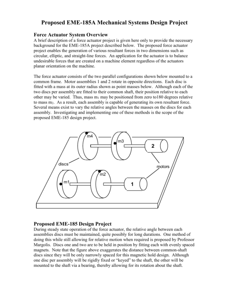
Proposed EME-185A Mechanical Systems Design Project Force Actuator System Overview A brief description of a force actuator project is given here only to provide the necessary background for the EME-185A project described below. The proposed force actuator project enables the generation of various resultant forces in two dimensions such as circular, elliptic, and straight-line forces. An application for the actuator is to balance undesirable forces that are created on a machine element regardless of the actuators planar orientation on the machine. The force actuator consists of the two parallel configurations shown below mounted to a common frame. Motor assemblies 1 and 2 rotate in opposite directions. Each disc is fitted with a mass at its outer radius shown as point masses below. Although each of the two discs per assembly are fitted to their common shaft, their position relative to each other may be varied. Thus, mass m1 may be positioned from zero to180 degrees relative to mass m2. As a result, each assembly is capable of generating its own resultant force. Several means exist to vary the relative angles between the masses on the discs for each assembly. Investigating and implementing one of these methods is the scope of the proposed EME-185 design project. m4 m3 2 discs motors m2 m1 1 Proposed EME-185 Design Project During steady state operation of the force actuator, the relative angle between each assemblies discs must be maintained, quite possibly for long durations. One method of doing this while still allowing for relative motion when required is proposed by Professor Margolis. Discs one and two are to be held in position by fitting each with evenly spaced magnets. Note that the figure above exaggerates the distance between common-shaft discs since they will be only narrowly spaced for this magnetic hold design. Although one disc per assembly will be rigidly fixed or “keyed” to the shaft, the other will be mounted to the shaft via a bearing, thereby allowing for its rotation about the shaft. To induce its rotation from one magnetically held position to the next, the following is proposed. If torque T is the normal running motor torque on the shaft, then let T be given by T = T + T1 where T1 is an additionally applied torque for a finite time. This T1 will be accomplished by way of a pulse supplied to the motor. In short, the goal is to pulse the motor such that temporary torque T will rotate the disc to its next magnetic position. Summary of Objectives Although many possible objectives for the project exist, they can be summarized into two main categories: 1.) Calculate the magnitude and duration required for torque T to rotate the disc to one or, possibly, multiple magnetic positions. This can be done based on a design for the magnetically-held disc pairs which is also encompassed in this project. Motors and their specifications will tentatively be supplied. 2.) Demonstrate the designs practicality by building and implementing it.


