File
advertisement
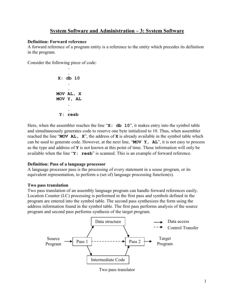
System Software and Administration – 3: System Software Definition: Forward reference A forward reference of a program entity is a reference to the entity which precedes its definition in the program. Consider the following piece of code: . . X: db 10 . . MOV AL, X MOV Y, AL . . Y: resb Here, when the assembler reaches the line “X: db 10”, it makes entry into the symbol table and simultaneously generates code to reserve one byte initialized to 10. Thus, when assembler reached the line “MOV AL, X”, the address of X is already available in the symbol table which can be used to generate code. However, at the next line, “MOV Y, AL”, it is not easy to process as the type and address of Y is not known at this point of time. These information will only be available when the line “Y: resb” is scanned. This is an example of forward reference. Definition: Pass of a language processor A language processor pass is the processing of every statement in a souse program, or its equivalent representation, to perform a (set of) language processing function(s). Two pass translation Two pass translation of an assembly language program can handle forward references easily. Location Counter (LC) processing is performed in the first pass and symbols defined in the program are entered into the symbol table. The second pass synthesizes the form using the address information found in the symbol table. The first pass performs analysis of the source program and second pass performs synthesis of the target program. Data access Control Transfer Data structure Source Program Pass 1 Pass 2 Target Program Intermediate Code Two pass translator 1 Single pass translation LC processing and construction of symbol table are done as in two pass translation. A technique called Back Patching is used to solve the problem of forward reference. The operand field of an instruction containing a forward reference is left blank initially. The address of the forward reference symbol is put into this field when its definition is encountered. In the program of the previous notes, the instruction corresponding to the statement MOVER BREG ONE can be partially synthesized since ONE is a forward reference. The memory location 101 (remember the directive START 101) contains the instruction opcode and address of BERG. For inserting the second operand’s address at a later stage, a data structure, called Table of Incomplete Instruction, is used. Each entry in the Table of Incomplete Instruction (TII) is of the form (<instruction address>, <symbol>), e.g. (101, ONE) in this case. When the END statement is processed, the symbol table would contain the address of all symbols defined in the source program and TII would contain information of all forward reference. The assembler can now process each entry in TII to complete the concerned instruction. Design of two pass assembler Tasks of a two pass assembler are segregated as follows: Pass 1 – Performs analysis of the source program & synthesis of the intermediate representation. The steps are: 1. Separate the symbol, mnemonic opcode and operand fields. 2. Build the symbol table. 3. Perform LC processing. 4. Construct intermediate representation. Pass 2 – Processes the intermediate representation to synthesize the target program. The steps are: 1. Synthesize the target program. Relationship between Pass 1 and Pass 2 of a two pass assembler Source program Pass 1 OPTAB SYMTAB Intermediate representation Pass 2 Object codes SYMTAB B 2 Literal handling A literal is an operand with the syntax =’<value>’. Following figure shows how literals can be handled in two steps: ADD AREG, =’5’ @FIVE ASSEMBLY LANGUAGE 1 2 3 4 LOOP 5 6 7 12 13 START MOVER MOVEM MOVER MOVER ADD ... BC LTORG NEXT LAST A BACK B ... SUB BC STOP ORIGIN MULT ORIGIN DS EQU DS END AREG, ‘5’ @FIVE MACHINE LANGUAGE 200 AREG, AREG, AREG, CREG, CREG, =’5’ A A B =’1’ 200) 201) 202) 203) 204) +04 +05 +04 +05 +01 ANY, NEXT 210) +07 6 214 211) 212) +00 0 005 +00 0 001 =’1’ BACK 214) 215) 216) +02 1 219 +07 1 202 +00 0 000 B 204) +03 3 218 =’5’ =’1’ 14 15 16 17 18 19 20 21 22 23 24 25 ADD DC AREG, LT, LOOP+2 CREG, LAST+1 1 LOOP 1 =’1’ 1 1 1 3 3 211 217 217 218 212 217) 218) 219) +00 0 001 Pass I uses the following data structures: OPTAB : A table of mnemonic opcodes and related information SYMTAB : Symbol table LITTAB : A table of literals used in the program POOLTAB : A table of information concerning literal pools OPTAB OPTAB contains the mnemonic opcode, class and mnemonic info. The class field indicates whether opcode is an imperative statement (IS), a declarative statement (DS) or an assembler directive (AD). In case the class is IS, the mnemonic info field contains the pair (machine opcode, instruction length); else it contains the id of a routine to handle the declarative or directive statement. 3 SYMTAB SYMTAB entries contain three fields: symbol, address and length. LITTAB LITTAB entries contain two fields: literal and address. Entries are in LITTAB are used in sequential manner. Each entry pertains to a literal. POOLTAB An entry in POOLTAB pertains to a pool of literals. It contains the single field literal number to indicate which entry in the LITTAB contains the first literal of the pool. OPTAB mnemonic opcode MOVER DS START class IS DL AD LITTAB value =’5’ =’1’ =’1’ address SYMTAB mnemonic info (04, 1) R#7 R#11 symbol LOOP NEXT LAST A BACK B address 202 214 216 217 202 218 length 1 1 1 1 1 1 POOLTAB first #1 #3 #4 literal number 2 1 0 Literal placement scheme in an assembler As soon as a literal is found in a statement, the assembler enters it into a literal pool unless a matching literal already exists in the pool. At every LTORG (origin of literal) and at the END statement, the assembler allocates addresses to the literals of the literal pool, starting with the current address in the location counter and the address in the location counter is appropriately incremented. The literal pool is then cleared. If a program does not use an LTORG statement, the assembler would enter all literals used in the program into a single pool and allocate memory to them when it encounters the END statement. Memory allocation to literals The assembler allocates memory to the literals used in the assembly language program in page 3. At first it enters 1 in the first entey of the POOLTAB to indicate that the first literal of the first literal pool occupies the first entry of LTTAB. The literals =’5’ and =’1’ are added to the literal pool in statements 2 and 6 respectively are entered in the first two entries of the LITTAB. The first LTORG statement (statement 13) allocates the addresses 211 and 212 to the values ’5’ and ’1’. Then the entry number of the first free entry in the LITTAB, which is 3, will be entered in the second entry of POOLTAB. A new literal pool is now started. The literal =’1’ 4 used in statement 15 will be entered in the third entry of LITTAB. This literal is allocated the address 219 while processing the END statement. Intermediate code form The Intermediate code consists of a sequence of intermediate code units (IC units). Each IC unit consists of the following fields. 1. Address 2. Representation of the mnemonic opcode 3. Representation of operands The format of the mnemonic opcode field is (statement class, code), where statement class is any one of imperative statement (IS), declarative statement (DS) or assembler directive (AD). code is instruction code in machine language (for an imperative statement), or is ordinal number within the class (for declarative statement and assembler directive). Code is an ordinal number within the class. 5
