Kapittel 21
advertisement
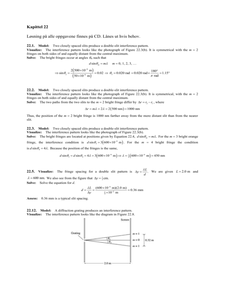
Kapittel 22 Løsning på alle oppgavene finnes på CD. Lånes ut hvis behov. 22.1. Model: Two closely spaced slits produce a double-slit interference pattern. Visualize: The interference pattern looks like the photograph of Figure 22.3(b). It is symmetrical with the m 2 fringes on both sides of and equally distant from the central maximum. Solve: The bright fringes occur at angles m such that d sin m m sin 2 2 500 109 m 50 10 6 m m 0, 1, 2, 3, … 0.02 2 0.020 rad 0.020 rad 180 rad 1.15 22.2. Model: Two closely spaced slits produce a double-slit interference pattern. Visualize: The interference pattern looks like the photograph of Figure 22.3(b). It is symmetrical, with the m 2 fringes on both sides of and equally distant from the central maximum. Solve: The two paths from the two slits to the m 2 bright fringe differ by r r2 r1 , where r m 2 2 500 nm 1000 nm Thus, the position of the m 2 bright fringe is 1000 nm farther away from the more distant slit than from the nearer slit. 22.3. Model: Two closely spaced slits produce a double-slit interference pattern. Visualize: The interference pattern looks like the photograph of Figure 22.3(b). Solve: The bright fringes are located at positions given by Equation 22.4, d sin m m. For the m 3 bright orange fringe, the interference condition is d sin 3 3 600 109 m . For the m 4 bright fringe the condition is d sin 4 4. Because the position of the fringes is the same, d sin 3 d sin 4 4 3 600 109 m 3 4 600 10 22.5. Visualize: The fringe spacing for a double slit pattern is y 9 L 600 nm. We also see from the figure that y 13 cm. Solve: Solve the equation for d. d L y (600 109 m)(20 m) 036 mm 1 102 m 3 Assess: 0.36 mm is a typical slit spacing. 22.12. Model: A diffraction grating produces an interference pattern. Visualize: The interference pattern looks like the diagram in Figure 22.8. m 450 nm d . We are given L 20 m and Solve: The bright fringes are given by Equation 22.15: m 0, 1, 2, 3, … d sin 1 1 d sin1 d sin m m The angle 1 can be obtained from geometry as follows: tan1 0.32 m 2 2.0 m 0.080 1 tan–1 (0.080) 4.57 Using sin1 sin 4.57 0.07968 , d 633 109 m 7.9 m 0.07968 22.15. Model: A narrow single slit produces a single-slit diffraction pattern. Visualize: The intensity pattern for single-slit diffraction will look like Figure 22.14. Solve: The minima occur at positions yp p So y y2 y1 L a 9 2 L 1 L L L 633 10 m 1.5 m a 2.0 104 m 0.20 mm a a a y 0.00475 m 22.16. Model: A narrow slit produces a single-slit diffraction pattern. Visualize: The intensity pattern for single-slit diffraction will look like Figure 22.14. Solve: The width of the central maximum for a slit of width a 200 is w 2 L 2 2.0 m 20 mm a 200 22.18. Visualize: Use Equation 22.22: w figure that w 10 cm. Solve: Solve the equation for a. a 2 L . We are given 600 nm and L 20 m. We see from the a 2 L 2(600 109 m)(20 m) 024 mm w 0010 m Assess: 0.24 mm is in the range of typical slit widths. 22.20. Model: The spacing between the two buildings is like a single slit and will cause the radio waves to be diffracted. Solve: Radio waves are electromagnetic waves that travel with the speed of light. The wavelength of the 800 MHz waves is 3 108 m/s 0.375 m 800 106 Hz To investigate the diffraction of these waves through the spacing between the two buildings, we can use the general condition for complete destructive interference: a sin p p (p 1, 2, 3, …) where a is the spacing between the buildings. Because the width of the central maximum is defined as the distance between the two p 1 minima on either side of the central maximum, we will use p 1 and obtain the angular width 21 from 0.375 m a sin1 1 sin 1 sin 1 1.43 a 15 m Thus, the angular width of the wave after it emerges from between the buildings is 2 1.43 2.86 2.9. 22.22. Model: Light passing through a circular aperture leads to a diffraction pattern that has a circular central maximum surrounded by a series of secondary bright fringes. Solve: The width of the central maximum for a circular aperture of diameter D is w 2.44 L (2.44)(500 109 m)(2.0 m) 4.9 mm 0.50 103 m D 22.34. Solve: According to Equation 22.7, the fringe spacing between the m fringe and the m 1 fringe is y L d . y can be obtained from Figure P22.34. The separation between the m 2 fringes is 2.0 cm implying that the separation between the two consecutive fringes is y 0.50 102 m L d L 1 4 (2.0 cm) 0.50 cm. Thus, d y 0.20 10 3 m 0.50 102 m 600 109 m 167 cm Assess: A distance of 167 cm from the slits to the screen is reasonable. 22.45. Model: A diffraction grating produces an interference pattern that is determined by both the slit spacing and the wavelength used. Solve: An 800 line/mm diffraction grating has a slit spacing d (1.0 103 m) 800 1.25 106 m. Referring to Figure P22.45, the angle of diffraction is given by tan1 y1 0.436 m 0.436 1 23.557 sin1 0.400 L 1.0 m Using the constructive-interference condition d sin m m , d sin1 1.25 106 m 0.400 500 nm 1 We can obtain the same value of by using the second-order interference fringe. We first obtain 2: tan 2 y2 0.436 m 0.897 m 1.333 2 53.12 sin 2 0.800 L 1.0 m Using the constructive-interference condition, 6 d sin 2 1.25 10 m 0.800 500 nm 2 2 Assess: Calculations with the first-order and second-order fringes of the interference pattern give the same value for the wavelength. 22.58. Model: The antenna is a circular aperture through which the microwaves diffract. Solve: (a) Within the small-angle approximation, the width of the central maximum of the diffraction pattern is w 2.44L/D. The wavelength of the radiation is c 3 108 m/s 2.44(0.025 m)(30 103 m) 0.025 m w 920 m 9 f 12 10 Hz 2.0 m That is, the diameter of the beam has increased from 2.0 m to 915 m, a factor of 458. (b) The average microwave intensity is I P 100 103 W 0.15 W/m2 area 12 915 m 2 22.59. Model: The laser beam is diffracted through a circular aperture. Visualize: Solve: (a) No. The laser light emerges through a circular aperture at the end of the laser. This aperture causes diffraction, hence the laser beam must gradually spread out. The diffraction angle is small enough that the laser beam appears to be parallel over short distances. But if you observe the laser beam at a large distance it is easy to see that the diameter of the beam is slowly increasing. (b) The position of the first minimum in the diffraction pattern is more or less the “edge” of the laser beam. For diffraction through a circular aperture, the first minimum is at an angle 1 9 1.22 1.22 633 10 m 5.15 104 rad 0.029 D 0.0015 m (c) The diameter of the laser beam is the width of the diffraction pattern: w 9 2.44 L 2.44 633 10 m 3 m 0.00309 m 0.31 cm D 0.0015 m (d) At L 1 km 1000 m, the diameter is 9 2.44 L 2.44 633 10 m 1000 m w 1.03 m 1.0 m D 0.0015 m

