3D-image processing in the compact reverse engineering systems
advertisement
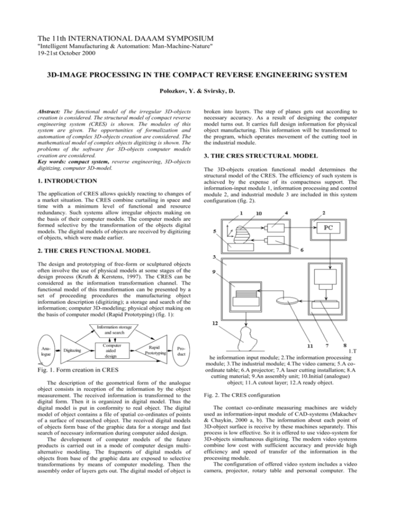
The 11th INTERNATIONAL DAAAM SYMPOSIUM "Intelligent Manufacturing & Automation: Man-Machine-Nature" 19-21st October 2000 3D-IMAGE PROCESSING IN THE COMPACT REVERSE ENGINEERING SYSTEM Polozkov, Y. & Svirsky, D. Abstract: The functional model of the irregular 3D-objects creation is considered. The structural model of compact reverse engineering system (CRES) is shown. The modules of this system are given. The opportunities of formalization and automation of complex 3D-objects creation are considered. The mathematical model of complex objects digitizing is shown. The problems of the software for 3D-objects computer models creation are considered. Key words: compact system, reverse engineering, 3D-objects digitizing, computer 3D-model. 1. INTRODUCTION The application of CRES allows quickly reacting to changes of a market situation. The CRES combine curtailing in space and time with a minimum level of functional and resource redundancy. Such systems allow irregular objects making on the basis of their computer models. The computer models are formed selective by the transformation of the objects digital models. The digital models of objects are received by digitizing of objects, which were made earlier. broken into layers. The step of planes gets out according to necessary accuracy. As a result of designing the computer model turns out. It carries full design information for physical object manufacturing. This information will be transformed to the program, which operates movement of the cutting tool in the industrial module. 3. THE CRES STRUCTURAL MODEL The 3D-objects creation functional model determines the structural model of the CRES. The efficiency of such system is achieved by the expense of its compactness support. The information-input module 1, information processing and control module 2, and industrial module 3 are included in this system configuration (fig. 2). 2. THE CRES FUNCTIONAL MODEL The design and prototyping of free-form or sculptured objects often involve the use of physical models at some stages of the design process (Kruth & Kerstens, 1997). The CRES can be considered as the information transformation channel. The functional model of this transformation can be presented by a set of proceeding procedures the manufacturing object information description (digitizing); a storage and search of the information; computer 3D-modeling; physical object making on the basis of computer model (Rapid Prototyping) (fig. 1): Information storage and search Analogue Digitazing Computer aided design Rapid Prototyping Product Fig. 1. Form creation in CRES The description of the geometrical form of the analogue object consists in reception of the information by the object measurement. The received information is transformed to the digital form. Then it is organized in digital model. Thus the digital model is put in conformity to real object. The digital model of object contains a file of spatial co-ordinates of points of a surface of researched object. The received digital models of objects form base of the graphic data for a storage and fast search of necessary information during computer aided design. The development of computer models of the future products is carried out in a mode of computer design multialternative modeling. The fragments of digital models of objects from base of the graphic data are exposed to selective transformations by means of computer modeling. Then the assembly order of layers gets out. The digital model of object is 1.T he information input module; 2.The information processing module; 3.The industrial module; 4.The video camera; 5.A coordinate table; 6.A projector; 7.A laser cutting installation; 8.A cutting material; 9.An assembly unit; 10.Initial (analogue) object; 11.A cutout layer; 12.A ready object. Fig. 2. The CRES configuration The contact co-ordinate measuring machines are widely used as information-input module of CAD-systems (Makachev & Chaykin, 2000 a, b). The information about each point of 3D-object surface is receive by these machines separately. This process is low effective. So it is offered to use video-system for 3D-objects simultaneous digitizing. The modern video systems combine low cost with sufficient accuracy and provide high efficiency and speed of transfer of the information in the processing module. The configuration of offered video system includes a video camera, projector, rotary table and personal computer. The projector is equipped with a slide with the image of a coordinate grid with the units, which located from each other on equally distance. The digitizing process includes a shooting of object, on which light strips of the slide inserted in the horizontal located projector are imaging, by the video camera established by angle to a horizontal plane. The 3D-stage information is imported from the video camera to the computer. In the computer the software organizes the information in digital models of objects. The object digital model making elements are the scanning object surface points co-ordinates in the chosen spatial system of co-ordinates. The module of information processing and control is functional invariant of all system. The interrelation between system making modules is carried out by it. Also in this module the computer model is developed. The industrial module realizes the technology of level-bylevel object manufacturing. It includes: a CO2-laser; the optical channel; a control system, a coordinate table. The layers parallel connection allows monolithic products making. The method of flat elements cross connection of allows 3D-object skeleton assembly. 4. FORMALIZATION AND AUTOMATION OF IRREGULAR SURFACES CREATION IN CRES The mathematical model of digitizing process of spatial objects with the help of video system was developed (Polozkov & Zavatsky, 1999). R ij A 1 ( )A 2 ( ) R x кA 3 ( )A 4 ( )A 5 ( )Sm , (1) where R ij = X ij ; Yij; Zij T - vector, determining a space of a ipoint of j-level of a surface of object in spatial system of coordinates; k - factor of scaling; A1, A2, , , R x - parameters determining a space of the project center; A3, A4, A5, , , parameters of orientation of system of co-ordinates concerning of the image system of co-ordinates of object; Sm - vector determining a space of the central projections of points of object in spatial system of co-ordinates. This mathematical model describes dependence between the position of points of a 3D-scanning object surface and the position of their central projections. It allows to transform 2Dparameters of the object video image in its 3D-parameters with the help of the following formulas: X ij X S z ij x ij (Htgx ij Z S ) z ij x ij tgx ij Zij (H Xij )tgxij Yij YS d ij (H Xij ) , fr Z ij Z S z ij , y ij , (2) (3) (4) where XS, YS, ZS - co-ordinates of a forward video camera central point in 3D-co-ordinates system; H - distance of scanning object up to a projections centre of the projector; ij angle of a direction of the projector central ray; ij - distance a grid j-line of a slide of a projector main optical axis; fr - focal distance of projector. This mathematical model allows the irregular 3D-objects digitizing process automating. The programming is carried out with use of known computer algebra software. The algorithm of recalculation of numerical parameters includes operations on formation of the list of the initial data, input of elements of numerical parameters from the received file and direct recording of teams of mathematical calculations which are carried out in a matrix kind. The received results are organized in files, which describe a spatial configuration of the object separate parties. Synthesizing the given files on boundary points, we receive volumetric digital model of object. The volumetric digital model of the object is a making component of the graphic database. The received volumetric digital model is exposed to selective transformation with the help of functions of computer modeling. As a result of designing the computer model carrying the design information for physical object manufacturing (Gubanov & Vlasov, 2000). In the industrial module the received computer model will be transformed to the tool control influences. The made elements can be assembled manually or automatically with the help of the manipulator. The process of assembly of discrete layers in integral object formally can be described by algebraically expression: n O = Sj (5) j=1 , where O - integral object; Sj - a j-layer of object; n – general quantity of the layers. 5. CONCLUSION The analysis of the complex 3D-objects creation functional model has allowed to develop variant of a compact industrial system. Video system using in this complex allows to solve a problem of this process information support. It allows also to speed up a manufacture preparation stage. The development of mathematical model digitizing and its software allows to create computer models easily. The application of level-by-level synthesis allows to make material irregular objects quickly. The offered variant of compact reverse engineering system allows to raise production competitiveness. 6. REFERENCES Gubanov, A. & Vlasov, V. (2000). Computer technologies of reverse engineering. CAD & Graphics, No 1, pp. 25-29, ISSN 1560-4640. Kruth, J. -P. & Kerstens, A. (1997). Reverse engineering modeling of free-form surfaces from point clouds subject to boundary conditions. Journal of Materials Processing Technology, No. 76, pp. 120-127, ISSN 0924-0136. Makachev, A. & Chaykin, (2000). Modeler 2000: 3D-scaning systems. CAD & Graphics, No 1, pp. 84-86, ISSN 15604640. Makachev, A. & Chaykin, (2000). Modeler 2000: 3D-scaning systems II. CAD & Graphics, No 4, pp. 76-78, ISSN 15604640. Polozkov, Y. & Zavatsky, Y. (1999). The mathematical software of irregular surfaces 3D-scaning. Proceedings of the international conference on the modern trends of industrial technologies development, Sazonov, I. et. al. (Ed.), p. 61, ISBN 5-86960-014-6, Mogilev machinebuilding institute, April 1999, MMI, Mogilev. Authors: Ing. Yuri POLOZKOV, Post-grad. of Vitebsk State Technological University, 72 Moskowsky ave., 210035 Vitebsk, Belarus, Phone: 375 212 25 55 45 Fax 375 212 25 74 01 Dr. Dmitry SVIRSKY, Science leader of the Computer Aided Design Centre, Vitebsk State Technological University, 72 Moskowsky ave., 210035 Vitebsk, Belarus, Phone: 375 212 22 70 41 Fax 375 212 25 74 01 E-mail: svirsky@vstu.unibel.by
